Nissan Altima 2007-2012 Service Manual: On-vehicle repair
HORN
Removal and Installation
REMOVAL
1. Position aside the front fender protector LH. Refer to EXT-19, "Removal and Installation".
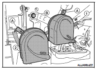
2. Disconnect the horn connectors (A).
3. Remove the horn bracket bolt (B), and remove horn (1) and horn (2) if equipped.
INSTALLATION
Installation is in the reverse order of removal.
Component diagnosis
Wiring Diagram - Coupe
Wiring Diagram - Sedan
...
Power Outtlet
...
Other materials:
B210a steering lock condition switch
Description
There are 2 switches in the steering unit. IPDM E/R compares those 2 switches
conditions to judge the
present steering status and transmit the result to BCM via CAN communication.
DTC Logic
DTC DETECTION LOGIC
NOTE:
• If DTC B210A is displayed with DTC U1000, first perform the ...
P0130 A/F Sensor 1
Description
The air fuel ratio (A/F) sensor 1 is a planar one-cell limit current sensor.
The sensor element of the A/F sensor 1 is composed an electrode
layer, which transports ions. It has a heater in the element.
The sensor is capable of precise measurement = 1, but also in the
lean and ...
DLC branch line circuit
Diagnosis Procedure
INSPECTION PROCEDURE
1.CHECK CONNECTOR
1. Turn the ignition switch OFF.
2. Disconnect the battery cable from the negative terminal.
3. Check the terminals and connectors of the data link connector for damage,
bend and loose connection
(connector side and harness side ...