Nissan Altima (L32) 2007-2012 Service Manual: On-vehicle repair
EVAP CANISTER
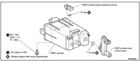
Exploded View
Removal and Installation
REMOVAL
1. Lift up the vehicle.
2. Remove EVAP canister fixing bolt.
3. Remove EVAP canister.
NOTE:
The EVAP canister vent control valve and EVAP canister system pressure sensor
can be removed without
removing the EVAP canister.
INSTALLATION
Install in the reverse order of removal.
NOTE:
Tighten EVAP canister fixing bolt to the specified torque.
DISASSEMBLY
1. Turn EVAP canister vent control valve counterclockwise.
A : Lock
B : Unlock
2. Remove the EVAP canister vent control valve.
ASSEMBLY
Assemble in the reverse order of disassembly.
CAUTION:
Always replace O-ring with a new one.
Inspection
Check EVAP canister as follows:
1. Block port (B).
2. Blow air into port (A) and check that it flows freely out of port (C).
3. Release blocked port (B).
4. Apply vacuum pressure to port (B) and check that vacuum pressure
exists at the ports (A) and (C).
5. Block port (A) and (B).
6. Apply pressure to port (C) and check that there is no leakage.
Inspection
CAUTION:
• Do not use compressed air or a high pressure pump.
• Do not exceed 4.12 kPa (0.042 kg/cm2, 0.6 psi) of pressure in EVAP system.
NOTE:
• Do not start engine.
• I ...
Idle Speed
*: Under the following conditions
• A/C switch: OFF
• Electric load: OFF (Lights, heater fan & rear window defogger)
• Steering wheel: Kept in straight-ahead position
Igni ...
Other materials: Programming HomeLink for Canadian
customers and gate openers
Canadian radio-frequency laws require
transmitter signals to "time-out" (or quit)
after several seconds of transmission -
which may not be long enough for
HomeLink to pick up the signal during
training. Similar to this Canadian law, some
U.S. gate operators are designed to "timeout"
in the same mann ...
Vehicle information display - 5 inch (13 cm) Type A (if so equipped)
The vehicle information display is located
to the left of the speedometer. It displays
such items as:
Vehicle settings
Indicators and warnings
Information/warning messages
Tire pressure information
Drive computer information
Cruise control system information
Driving Aids (if so equipped)
N ...
NISSAN Intelligent Key System
WARNING
Radio waves could adversely affect
electric medical equipment. Those
who use a pacemaker should contact
the electric medical equipment
manufacturer for the possible influences
before use.
The Intelligent Key transmits radio
waves when the buttons are pressed.
The FAA advises the ra ...
 Evap leak check
 Service data and specifications
(SDS)
Service data and specifications
(SDS)