Nissan Altima (L32) 2007-2012 Service Manual: P0011 IVT Control
DTC Logic
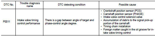
DTC DETECTION LOGIC
NOTE: If DTC P0011 is displayed with DTC P0075, first perform the trouble diagnosis for EC-867, "DTC Logic".
DTC CONFIRMATION PROCEDURE
1.PRECONDITIONING
If DTC Confirmation Procedure has been previously conducted, always turn ignition switch OFF and wait at least 10 seconds before conducting the next test.
TESTING CONDITION: Before performing the following procedure, confirm that battery voltage is between 10V and 16V at idle.
>> GO TO 2.
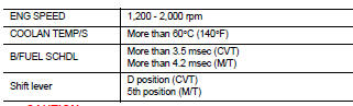
2.PERFORM DTC CONFIRMATION PROCEDURE-I

1. Turn ignition switch ON and select “DATA MONITOR” mode with CONSULT-III.
2. Start engine and warm it up to the normal operating temperature.
3. Maintain the following conditions for at least 6 consecutive seconds. Hold the accelerator pedal as steady as possible.
CAUTION: Always drive at a safe speed.
4. Stop vehicle with engine running and let engine idle for 10 seconds.
5. Check 1st trip DTC.

Follow the procedure “With CONSULT-III” above.
Is 1st trip DTC detected? YES >> Go to EC-681, "Diagnosis Procedure" NO >> GO TO 3.
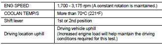
3.PERFORM DTC CONFIRMATION PROCEDURE-II

1. Maintain the following conditions for at least 20 consecutive seconds.
CAUTION: Always drive at a safe speed.
2. Check 1st trip DTC.

Follow the procedure “With CONSULT-III” above.
Is 1st trip DTC detected? YES >> Go to EC-681, "Diagnosis Procedure" NO >> INSPECTION END
Diagnosis Procedure
1.CHECK OIL PRESSURE WARNING LAMP
1. Start engine.
2. Check oil pressure warning lamp and confirm it is not illuminated.
Is oil pressure warning lamp illuminated? YES >> Go to LU-9, "Inspection".
NO >> GO TO 2.
2.CHECK INTAKE VALVE TIMING CONTROL SOLENOID VALVE
Refer to EC-682, "Component Inspection".
Is the inspection result normal? YES >> GO TO 3.
NO >> Replace intake valve timing control solenoid valve.
3.CHECK CRANKSHAFT POSITION SENSOR (POS)
Refer to EC-786, "Component Inspection".
Is the inspection result normal? YES >> GO TO 4.
NO >> Replace crankshaft position sensor (POS).
4.CHECK CAMSHAFT POSITION SENSOR (PHASE)
Refer to EC-789, "Component Inspection".
Is the inspection result normal? YES >> GO TO 5.
NO >> Replace camshaft position sensor (PHASE).
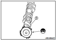
5.CHECK CAMSHAFT (INTAKE)
Check the following.
• Accumulation of debris to the signal plate of camshaft (1) rear end • Chipping signal plate of camshaft rear end
Is the inspection result normal? YES >> GO TO 6.
NO >> Remove debris and clean the signal plate of camshaft rear end or replace camshaft.
6.CHECK TIMING CHAIN INSTALLATION
Check service records for any recent repairs that may cause timing chain misaligned.
Are there any service records that may cause timing chain misaligned? YES >> Check timing chain installation. Refer to EM-52, "Removal and Installation".
NO >> GO TO 7.
7.CHECK LUBRICATION CIRCUIT
Refer to EM-48, "Inspection After Installation".
Is the inspection result normal? YES >> GO TO 8.
NO >> Clean lubrication line.
8.CHECK INTERMITTENT INCIDENT
Refer to GI-42, "Intermittent Incident".
>> INSPECTION END
Component Inspection
1.CHECK INTAKE VALVE TIMING CONTROL SOLENOID VALVE-I
1. Turn ignition switch OFF.
2. Disconnect intake valve timing control solenoid valve harness connector.
3. Check resistance between intake valve timing control solenoid valve terminals as follows.
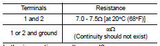
Is the inspection result normal? YES >> GO TO 2.
NO >> Replace intake valve timing control solenoid valve.
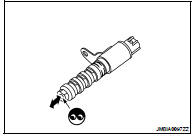
2.CHECK INTAKE VALVE TIMING CONTROL SOLENOID VALVE-II
1. Remove intake valve timing control solenoid valve.
2. Provide 12V DC between intake valve timing control solenoid valve terminals 1 and 2, and then interrupt it. Make sure that the plunger moves as shown in the figure.
CAUTION: Do not apply 12V DC continuously for 5 seconds or more.
Doing so may result in damage to the coil in intake valve timing control solenoid valve.
NOTE: Always replace O-ring when intake valve timing control solenoid valve is removed.
Is the inspection result normal? YES >> INSPECTION END
NO >> Replace intake valve timing control solenoid valve.
 U1001 Can comm circuit
 P0031, P0032 A/F Sensor 1 heater