Nissan Altima (L32) 2007-2012 Service Manual: P0300, P0301, P0302, P0303, P0304 misfire
DTC Logic
DTC DETECTION LOGIC
When a misfire occurs, engine speed will fluctuate. If the engine speed fluctuates enough to cause the crankshaft position (CKP) sensor (POS) signal to vary, ECM can determine that a misfire is occurring.

The misfire detection logic consists of the following two conditions.
1. One Trip Detection Logic (Three Way Catalyst Damage) On the 1st trip, when a misfire condition occurs that can damage the three way catalyst (TWC) due to overheating, the MIL will blink.
When a misfire condition occurs, the ECM monitors the CKP sensor signal every 200 engine revolutions for a change.
When the misfire condition decreases to a level that will not damage the TWC, the MIL will turn off.
If another misfire condition occurs that can damage the TWC on a second trip, the MIL will blink.
When the misfire condition decreases to a level that will not damage the TWC, the MIL will remain on.
If another misfire condition occurs that can damage the TWC, the MIL will begin to blink again.
2. Two Trip Detection Logic (Exhaust quality deterioration) For misfire conditions that will not damage the TWC (but will affect vehicle emissions), the MIL will only light when the misfire is detected on a second trip. During this condition, the ECM monitors the CKP sensor signal every 1,000 engine revolutions.
A misfire malfunction can be detected on any one cylinder or on multiple cylinders.

DTC CONFIRMATION PROCEDURE
1.PRECONDITIONING
If DTC Confirmation Procedure has been previously conducted, always turn ignition switch OFF and wait at least 10 seconds before conducting the next test.
>> GO TO 2.
2.PERFORM DTC CONFIRMATION PROCEDURE-I
1. Start engine and warm it up to normal operating temperature.
2. Turn ignition switch OFF and wait at least 10 seconds.
3. Restart engine and let it idle for about 15 minutes.
4. Check 1st trip DTC.
Is 1st trip DTC detected? YES >> Go to EC-272, "Diagnosis Procedure".
NO >> GO TO 3.
3.PERFORM DTC CONFIRMATION PROCEDURE-II
1. Turn ignition switch OFF and wait at least 10 seconds.
2. Start engine and drive the vehicle under the similar conditions to (1st trip) Freeze Frame Data for a certain time. Refer to the table below.
Hold the accelerator pedal as steady as possible.
The similar conditions to (1st trip) Freeze Frame Data means the vehicle operation that the following conditions should be satisfied at the same time.
CAUTION: Always drive vehicle in safe manner according to traffic conditions and obey all traffic laws when driving.
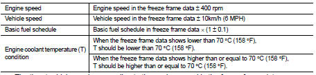
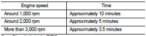
The time to driving varies according to the engine speed in the freeze frame data.
3. Check 1st trip DTC.
Is 1st trip DTC detected? YES >> Go to EC-272, "Diagnosis Procedure".
NO >> INSPECTION END
Diagnosis Procedure
1.CHECK FOR INTAKE AIR LEAK AND PCV HOSE
1. Start engine and run it at idle speed.
2. Listen for the sound of the intake air leak.
3. Check PCV hose connection.
Is intake air leak detected? YES >> Discover air leak location and repair.
NO >> GO TO 2.
2.CHECK FOR EXHAUST SYSTEM CLOGGING
Stop engine and visually check exhaust tube, three way catalyst and muffler for dents.
Is the inspection result normal? YES-1 >> With CONSULT-III: GO TO 3.
YES-2 >> Without CONSULT-III: GO TO 4.
NO >> Repair or replace it.
3.PERFORM POWER BALANCE TEST

1. Start engine.
2. Perform “POWER BALANCE” in “ACTIVE TEST” mode with CONSULT-III.
3. Make sure that each circuit produces a momentary engine speed drop.
Is the inspection result normal? YES >> GO TO 9.
NO >> GO TO 4.
4.CHECK FUNCTION OF FUEL INJECTOR
1. Start engine and let engine idle.
2. Listen to each fuel injector operating sound.
Clicking noise should be heard.
Is the inspection result normal? YES >> GO TO 5.
NO >> Perform trouble diagnosis for FUEL INJECTOR, refer to EC-464, "Component Inspection".
5.CHECK FUNCTION OF IGNITION COIL-I
CAUTION: Do the following procedure in the place where ventilation is good without the combustible.
1. Turn ignition switch OFF.
2. Remove fuel pump fuse in IPDM E/R to release fuel pressure.
NOTE: Do not use CONSULT-III to release fuel pressure, or fuel pressure applies again during the following procedure.
3. Start engine.
4. After engine stalls, crank it two or three times to release all fuel pressure.
5. Turn ignition switch OFF.
6. Remove all ignition coil harness connectors to avoid the electrical discharge from the ignition coils.
7. Remove ignition coil and spark plug of the cylinder to be checked.
8. Crank engine for 5 seconds or more to remove combustion gas in the cylinder.
9. Connect spark plug and harness connector to ignition coil.
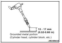
10. Fix ignition coil using a rope etc. with gap of 13 - 17 mm (0.52 - 0.66 in) between the edge of the spark plug and grounded metal portion as shown in the figure.
11. Crank engine for about 3 seconds, and check whether spark is generated between the spark plug and the grounded metal portion.
Spark should be generated.
CAUTION: • Do not approach to the spark plug and the ignition coil within 50 cm (19.7 in). Be careful not to get an electrical shock while checking, because the electrical discharge voltage becomes 20kV or more.
• It might cause to damage the ignition coil if the gap of more than 17 mm (0.66 in) is taken.
NOTE: When the gap is less than 13 mm (0.52 in), the spark might be generated even if the coil is malfunctioning.
Is the inspection result normal? YES >> GO TO 9.
NO >> GO TO 6.
6.CHECK FUNCTION OF IGNITION COIL-II
1. Turn ignition switch OFF.
2. Disconnect spark plug and connect a known-good spark plug.
3. Crank engine for about 3 seconds, and recheck whether spark is generated between the spark plug and the grounded metal portion.
Spark should be generated.
Is the inspection result normal? YES >> GO TO 7.
NO >> Check ignition coil, power transistor and their circuits. Refer to EC-470, "Component Function Check".
7.CHECK SPARK PLUG
Check the initial spark plug for fouling, etc.
Is the inspection result normal? YES >> Replace spark plug(s) with standard type one(s). For spark plug type, refer to EM-99, "Standard and Limit".
NO >> Repair or clean spark plug. Then GO TO 8.
8.CHECK FUNCTION OF IGNITION COIL-III
1. Reconnect the initial spark plugs.
2. Crank engine for about 3 seconds, and recheck whether spark is generated between the spark plug and the grounded portion.
Spark should be generated.
Is the inspection result normal? YES >> INSPECTION END NO >> Replace spark plug(s) with standard type one(s). For spark plug type, refer to EM-99, "Standard and Limit".
9.CHECK COMPRESSION PRESSURE
Check compression pressure. Refer to EM-23, "Compression pressure".
Is the inspection result normal? YES >> GO TO 10.
NO >> Check pistons, piston rings, valves, valve seats and cylinder head gaskets.
10.CHECK FUEL PRESSURE
1. Install all removed parts.
2. Check fuel pressure. Refer to EC-550, "Inspection".
Is the inspection result normal? YES >> GO TO 12.
NO >> GO TO 11.
11.DETECT MALFUNCTIONING PART
Check fuel hoses and fuel tubes for clogging.
Is the inspection result normal? YES >> Replace “fuel filter and fuel pump assembly”.
NO >> Repair or replace.
12.CHECK IGNITION TIMING
Check the following items. Refer to EC-24, "BASIC INSPECTION : Special Repair Requirement".
For specification, refer to EC-555, "Ignition Timing".
Is the inspection result normal? YES >> GO TO 13.
NO >> Follow the EC-24, "BASIC INSPECTION : Special Repair Requirement".
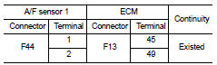
13.CHECK A/F SENSOR 1 INPUT SIGNAL CIRCUIT
1. Turn ignition switch OFF.
2. Disconnect corresponding A/F sensor 1 harness connector.
3. Disconnect ECM harness connector.
4. Check the continuity between A/F sensor 1 harness connector and ECM harness connector.
5. Check the continuity between A/F sensor 1 harness connector or ECM harness connector and ground.
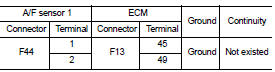
6. Also check harness for short to power.
Is the inspection result normal? YES >> GO TO 14.
NO >> Repair open circuit or short to ground or short to power in harness or connectors.
14.CHECK A/F SENSOR 1 HEATER
Refer to EC-157, "Component Inspection".
Is the inspection result normal? YES >> GO TO 15.
NO >> Replace A/F sensor 1.
15.CHECK MASS AIR FLOW SENSOR

Check “MASS AIR FLOW” in “DATA MONITOR” mode with CONSULT-III.
For specification, refer toEC-555, "Mass Air Flow Sensor".

Check mass air flow sensor signal in Service $01 with GST.
For specification, refer toEC-555, "Mass Air Flow Sensor".
Is the measurement value within the specification? YES >> GO TO 16.
NO >> Check connectors for rusted terminals or loose connections in the mass air flow sensor circuit or ground. Refer to EC-168, "DTC Logic".
16.CHECK SYMPTOM TABLE
Check items on the rough idle symptom in EC-539, "Symptom Table".
Is the inspection result normal? YES >> GO TO 17.
NO >> Repair or replace.
17.ERASE THE 1ST TRIP DTC
Some tests may cause a 1st trip DTC to be set.
Erase the 1st trip DTC from the ECM memory after performing the tests. Refer to EC-112, "Diagnosis Description".
>> GO TO 18.
18.CHECK INTERMITTENT INCIDENT
Refer to GI-42, "Intermittent Incident".
>> INSPECTION END
 P0222, P0223 TP sensor
 P0327, P0328 KS