Nissan Altima (L32) 2007-2012 Service Manual: P0335 CKP sensor (POS)
Description
The crankshaft position sensor (POS) is located on the oil pan facing the gear teeth (cogs) of the signal plate. It detects the fluctuation of the engine revolution.
The sensor consists of a permanent magnet and Hall IC.
When the engine is running, the high and low parts of the teeth cause the gap with the sensor to change.
The changing gap causes the magnetic field near the sensor to change.
Due to the changing magnetic field, the voltage from the sensor changes.
The ECM receives the voltage signal and detects the fluctuation of the engine revolution.
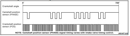
ECM receives the signals as shown in the figure.
DTC Logic
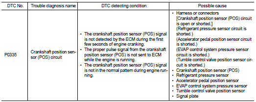
DTC DETECTION LOGIC
DTC CONFIRMATION PROCEDURE
1.PRECONDITIONING
If DTC Confirmation Procedure has been previously conducted, always turn ignition switch OFF and wait at least 10 seconds before conducting the next test.
TESTING CONDITION: Before performing the following procedure, confirm that battery voltage is more than 10.5V with ignition switch ON.
>> GO TO 2.
2.PERFORM DTC CONFIRMATION PROCEDURE
1. Start engine and let it idle for at least 5 seconds.
If engine does not start, crank engine for at least 2 seconds.
2. Check 1st trip DTC.
Is 1st trip DTC detected? YES >> Go to EC-279, "Diagnosis Procedure".
NO >> INSPECTION END
Diagnosis Procedure
1.CHECK GROUND CONNECTION
1. Turn ignition switch OFF.
2. Check ground connection E9. Refer to Ground Inspection in GI-45, "Circuit Inspection".
Is the inspection result normal? YES >> GO TO 2.
NO >> Repair or replace ground connection.
2.CHECK CRANKSHAFT POSITION (CKP) SENSOR (POS) POWER SUPPLY CIRCUIT-I
1. Disconnect crankshaft position (CKP) sensor (POS) harness connector.
2. Turn ignition switch ON.
3. Check the voltage between CKP sensor (POS) harness connector and ground.
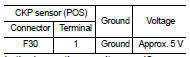
Is the inspection result normal? YES >> GO TO 8.
NO >> GO TO 3.
3.CHECK CRANKSHAFT POSITION (CKP) SENSOR (POS) POWER SUPPLY CIRCUIT-II
1. Turn ignition switch ON.
2. Disconnect ECM harness connector.
3. Check the continuity between CKP sensor (POS) harness connector and ECM harness connector.
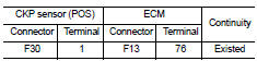
Is the inspection result normal? YES >> GO TO 4.
NO >> Repair open circuit.
4.CHECK CRANKSHAFT POSITION (CKP) SENSOR (POS) POWER SUPPLY CIRCUIT-III
Check harness for short to power and short to ground, between the following terminals.
Is the inspection result normal? YES >> GO TO 5.
NO >> Repair short to ground or short to power in harness or connectors.
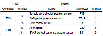
5.CHECK COMPONENTS
Check the following.
• Refrigerant pressure sensor (Refer to EC-482, "Diagnosis Procedure".) • EVAP control system pressure sensor (Refer to EC-318, "Component Inspection".) • Tumble control valve position sensor (Refer to EC-410, "Diagnosis Procedure".) Is the inspection result normal? YES >> GO TO 6.
NO >> Replace malfunctioning components.
6.CHECK APP SENSOR
Refer to EC-441, "Component Inspection".
Is the inspection result normal? YES >> GO TO 12.
NO >> GO TO 7.
7.REPLACE ACCELERATOR PEDAL ASSEMBLY
1. Replace accelerator pedal assembly.
2. Go to EC-29, "ACCELERATOR PEDAL RELEASED POSITION LEARNING : Special Repair Requirement".
>> INSPECTION END
8.CHECK CKP SENSOR (POS) GROUND CIRCUIT FOR OPEN AND SHORT
1. Turn ignition switch OFF.
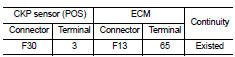
2. Check the continuity between CKP sensor (POS) harness connector and ECM harness connector.
3. Also check harness for short to ground and short to power.
Is the inspection result normal? YES >> GO TO 9.
NO >> Repair open circuit or short to ground or short to power in harness or connectors.
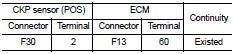
9.CHECK CKP SENSOR (POS) INPUT SIGNAL CIRCUIT FOR OPEN AND SHORT
1. Disconnect ECM harness connector.
2. Check the continuity between CKP sensor (POS) harness connector and ECM harness connector.
3. Also check harness for short to ground and short to power.
Is the inspection result normal? YES >> GO TO 10.
NO >> Repair open circuit or short to ground or short to power in harness or connectors.
10.CHECK CRANKSHAFT POSITION SENSOR (POS)
Refer to EC-281, "Component Inspection".
Is the inspection result normal? YES >> GO TO 11.
NO >> Replace crankshaft position sensor (POS).
11.CHECK GEAR TOOTH
Visually check for chipping signal plate gear tooth.
Is the inspection result normal? YES >> GO TO 12.
NO >> Replace the signal plate.
12.CHECK INTERMITTENT INCIDENT
Refer to GI-42, "Intermittent Incident".
>> INSPECTION END
Component Inspection
1.CHECK CRANKSHAFT POSITION SENSOR (POS)-I
1. Turn ignition switch OFF.
2. Loosen the fixing bolt of the sensor.
3. Disconnect crankshaft position sensor (POS) harness connector.
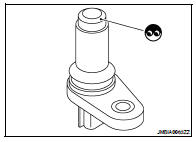
4. Remove the sensor.
5. Visually check the sensor for chipping.
Is the inspection result normal? YES >> GO TO 2.
NO >> Replace crankshaft position sensor (POS).
2.CHECK CRANKSHAFT POSITION SENSOR (POS)-II
Check resistance between crankshaft position sensor (POS) terminals as follows.
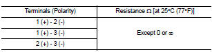
Is the inspection result normal? YES >> INSPECTION END
NO >> Replace crankshaft position sensor (POS).
 P0327, P0328 KS
 P0340 CMP sensor (phase)