Nissan Altima (L32) 2007-2012 Service Manual: P0448 evap canister vent control valve
Description
The EVAP canister vent control valve is located on the EVAP canister and is used to seal the canister vent.
This solenoid valve responds to signals from the ECM. When the ECM sends an ON signal, the coil in the solenoid valve is energized.
A plunger will then move to seal the canister vent. The ability to seal the vent is necessary for the on board diagnosis of other evaporative emission control system components.
This solenoid valve is used only for diagnosis, and usually remains opened.
When the vent is closed, under normal purge conditions, the evaporative emission control system is depressurized and allows “EVAP Control System” diagnosis.
DTC Logic
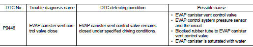
DTC DETECTION LOGIC
DTC CONFIRMATION PROCEDURE
1.PRECONDITIONING
If DTC Confirmation Procedure has been previously conducted, always turn ignition switch OFF and wait at least 10 seconds before conducting the next test.
>> GO TO 2.
2.PERFORM DTC CONFIRMATION PROCEDURE

1. Turn ignition switch ON and wait at least 5 seconds.
2. Turn ignition switch OFF and wait at least 10 seconds.
3. Turn ignition switch ON and select “DATA MONITOR” mode with CONSULT-III.
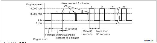
4. Start engine and let it idle for at least 1 minute.
5. Repeat next procedures three times.
- Increase the engine speed up to 3,000 to 3,500 rpm and keep it for 2 minutes and 50 seconds to 3 minutes.
Never exceed 3 minutes.
- Fully released accelerator pedal and keep engine idle for about 5 seconds.
6. Repeat next procedure 20 times.
- Quickly increase the engine speed up to 4,000 to 4,500 rpm or more and keep it for 25 to 30 seconds.
- Fully released accelerator pedal and keep engine idle for at least 35 seconds.
7. Check 1st trip DTC.

Follow the procedure “With CONSULT-III” above.
Is 1st trip DTC detected? YES >> Go to EC-819, "Diagnosis Procedure".
NO >> INSPECTION END
Diagnosis Procedure
1.CHECK RUBBER TUBE
1. Turn ignition switch OFF.
2. Disconnect rubber tube connected to EVAP canister vent control valve.
3. Check the rubber tube for clogging.
Is the inspection result normal? YES >> GO TO 2.
NO >> Clean rubber tube using an air blower.
2.CHECK EVAP CANISTER VENT CONTROL VALVE
Refer to EC-820, "Component Inspection".
Is the inspection result normal? YES >> GO TO 3.
NO >> Replace EVAP canister vent control valve.
3.CHECK IF EVAP CANISTER SATURATED WITH WATER
1. Remove EVAP canister with EVAP canister vent control valve and EVAP control system pressure sensor attached.
2. Check if water will drain from the EVAP canister.
Does water drain from EVAP canister? YES >> GO TO 4.
NO >> GO TO 6.
4.CHECK EVAP CANISTER
Weigh the EVAP canister with the EVAP canister vent control valve and EVAP control system pressure sensor attached.
The weight should be less than 2.1 kg (4.6 lb).
Is the inspection result normal? YES >> GO TO 6.
NO >> GO TO 5.
5.DETECT MALFUNCTIONING PART
Check the following.
• EVAP canister for damage
• EVAP hose between EVAP canister and vehicle frame for clogging or poor connection
>> Repair hose or replace EVAP canister.
6.CHECK EVAP CONTROL SYSTEM PRESSURE SENSOR CONNECTOR
1. Disconnect EVAP control system pressure sensor harness connector.
2. Check connectors for water.
Water should not exist.
Is the inspection result normal? YES >> GO TO 7.
NO >> Replace EVAP control system pressure sensor.
7.CHECK EVAP CONTROL SYSTEM PRESSURE SENSOR
Refer to EC-824, "Component Inspection".
Is the inspection result normal? YES >> GO TO 8.
NO >> Replace EVAP control system pressure sensor.
8.CHECK INTERMITTENT INCIDENT
Refer to GI-42, "Intermittent Incident".
>> INSPECTION END
Component Inspection
1.CHECK EVAP CANISTER VENT CONTROL VALVE-I
1. Turn ignition switch OFF.
2. Remove EVAP canister vent control valve from EVAP canister.
3. Check portion (A) of EVAP canister vent control valve for being rusted.
Is it rusted? YES >> Replace EVAP canister vent control valve
NO >> GO TO 2.
2.CHECK EVAP CANISTER VENT CONTROL VALVE-II

1. Reconnect harness connectors disconnected.
2. Turn ignition switch ON.
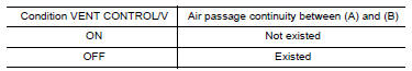
3. Perform “VENT CONTROL/V” in “ACTIVE TEST” mode.
4. Check air passage continuity and operation delay time.
Make sure new O-ring is installed properly.
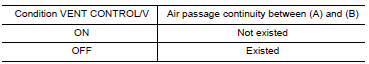
Operation takes less than 1 second.

Check air passage continuity and operation delay time under the following conditions.
Make sure new O-ring is installed properly.
Operation takes less than 1 second.
Is the inspection result normal? YES >> INSPECTION END
NO >> Replace EVAP canister vent control valve
3.CHECK EVAP CANISTER VENT CONTROL VALVE-III

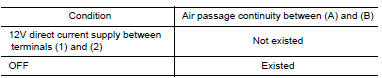
1. Clean the air passage [portion (A) to (B)] of EVAP canister vent control valve using an air blower.
2. Perform “VENT CONTROL/V” in “ACTIVE TEST” mode.
3. Check air passage continuity and operation delay time.
Make sure new O-ring is installed properly.
Operation takes less than 1 second.

1. Clean the air passage [portion (A) to (B)] of EVAP canister vent control valve using an air blower.
2. Check air passage continuity and operation delay time under the following conditions.
Make sure new O-ring is installed properly.
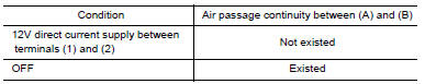
Operation takes less than 1 second.
Is the inspection result normal? YES >> INSPECTION END
NO >> GO TO 3.
 P0447 evap canister vent control
valve
P0447 evap canister vent control
valve P0451 evap control system pressure
sensor
P0451 evap control system pressure
sensor