Nissan Altima (L32) 2007-2012 Service Manual: P0453 Evap control system pressure sensor
Description
The EVAP control system pressure sensor detects pressure in the purge line. The sensor output voltage to the ECM increases as pressure increases.
DTC Logic
DTC DETECTION LOGIC
DTC CONFIRMATION PROCEDURE
1.PRECONDITIONING
If DTC Confirmation Procedure has been previously conducted, always perform the following before conducting the next test.
1. Turn ignition switch OFF and wait at least 10 seconds.
2. Turn ignition switch ON.
3. Turn ignition switch OFF and wait at least 10 seconds.
TESTING CONDITION: Always perform test at a temperature of 5°C (41°F) or more.
>> GO TO 2.
2.PERFORM DTC CONFIRMATION PROCEDURE

1. Start engine and warm it up to normal operating temperature.
2. Turn ignition switch OFF and wait at least 10 seconds.
3. Turn ignition switch ON.
4. Turn ignition switch OFF and wait at least 10 seconds.
5. Turn ignition switch ON.
6. Select “DATA MONITOR” mode with CONSULT-III.
7. Check that “FUEL T/TMP SE” is more than 0°C (32°F).
8. Start engine and wait at least 20 seconds.
9. Check 1st trip DTC.

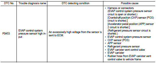
1. Start engine and warm it up to normal operating temperature.
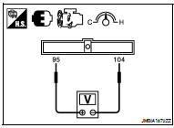
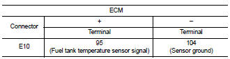
2. Set voltmeter probes to ECM harness connector terminals.
3. Check that the voltage is less than 4.2 V.
4. Turn ignition switch OFF and wait at least 10 seconds.
5. Turn ignition switch ON.
6. Turn ignition switch OFF and wait at least 10 seconds.
7. Start engine and wait at least 20 seconds.
8. Check 1st trip DTC.
Is 1st trip DTC detected? YES >> Go to EC-1341, "Diagnosis Procedure".
NO >> INSPECTION END
Diagnosis Procedure
1.CHECK GROUND CONNECTION
1. Turn ignition switch OFF.
2. Check ground connection E9. Refer to Ground Inspection in GI-45, "Circuit Inspection".
Is the inspection result normal? YES >> GO TO 2.
NO >> Repair or replace ground connection.
2.CHECK CONNECTOR
1. Disconnect EVAP control system pressure sensor harness connector.
2. Check that water is not inside connectors.
Is the inspection result normal? YES >> GO TO 3.
NO >> Repair or replace harness connector.
3.CHECK EVAP CONTROL SYSTEM PRESSURE SENSOR POWER SUPPLY CIRCUIT
1. Turn ignition switch ON.
2. Check the voltage between EVAP control system pressure sensor harness connector and ground.
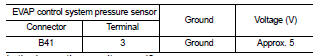
Is the inspection result normal? YES >> GO TO 10.
NO >> GO TO 4.
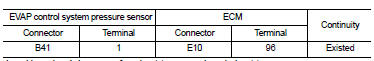
4.CHECK EVAP CONTROL SYSTEM PRESSURE SENSOR POWER SUPPLY CIRCUIT-II
1. Turn ignition switch OFF.
2. Disconnect ECM harness connector.
3. Check the continuity between EVAP control system pressure sensor harness connector and ECM harness connector.
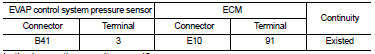
Is the inspection result normal? YES >> GO TO 6.
NO >> GO TO 5.
5.DETECT MALFUNCTIONING PART
Check the following.
• Harness connectors B10, E29
• Harness for open or short between EVAP control system pressure sensor and ECM
>> Repair open circuit.
6.CHECK SENSOR POWER SUPPLY CIRCUIT
Check harness for short to power and short to ground, between the following terminals.
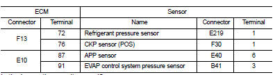
Is the inspection result normal? YES >> GO TO 7.
NO >> Repair short to ground or short to power in harness or connectors.
7.CHECK COMPONENTS
Check the following.
• Crankshaft position sensor (POS) (Refer to EC-1295, "Component Inspection".) • Refrigerant pressure sensor (Refer to EC-1503, "Diagnosis Procedure".) Is the inspection result normal? YES >> GO TO 8.
NO >> Replace malfunctioning components.
8.CHECK APP SENSOR
Refer to EC-1450, "Component Inspection".
Is the inspection result normal? YES >> GO TO 15.
NO >> GO TO 9.
9.REPLACE ACCELERATOR PEDAL ASSEMBLY
1. Replace accelerator pedal assembly.
2. Refer to EC-1450, "Special Repair Requirement".
>> INSPECTION END
10.CHECK EVAP CONTROL SYSTEM PRESSURE SENSOR GROUND CIRCUIT FOR OPEN AND SHORT
1. Turn ignition switch OFF.
2. Disconnect ECM harness connector.
3. Check the continuity between EVAP control system pressure sensor harness connector and ECM harness connector.
4. Also check harness for short to ground and short to power.
Is the inspection result normal? YES >> GO TO 12.
NO >> GO TO 11.
11.DETECT MALFUNCTIONING PART
Check the following.
• Harness connectors B10, E29
• Harness for open or short between EVAP control system pressure sensor and ECM
>> Repair open circuit, short to ground or short to power in harness or connectors.
12.CHECK EVAP CONTROL SYSTEM PRESSURE SENSOR INPUT SIGNAL CIRCUIT FOR OPEN AND SHORT
1. Check the continuity between EVAP control system pressure sensor harness connector and ECM harness connector.
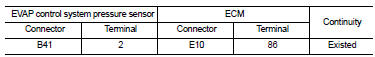
2. Also check harness for short to ground and short to power.
Is the inspection result normal? YES >> GO TO 14.
NO >> GO TO 13.
13.DETECT MALFUNCTIONING PART
Check the following.
• Harness connectors B10, E29
• Harness for open or short between EVAP control system pressure sensor and ECM
>> Repair open circuit, short to ground or short to power in harness or connectors.
14.CHECK RUBBER TUBE
1. Disconnect rubber tube connected to EVAP canister vent control valve.
2. Check the rubber tube for clogging.
Is the inspection result normal? YES >> GO TO 15.
NO >> Clean the rubber tube using an air blower, repair or replace rubber tube.
15.CHECK EVAP CANISTER VENT CONTROL VALVE
Refer to EC-1326, "Component Inspection".
Is the inspection result normal? YES >> GO TO 16.
NO >> Replace EVAP canister vent control valve.
16.CHECK EVAP CONTROL SYSTEM PRESSURE SENSOR
Refer to EC-1344, "Component Inspection".
Is the inspection result normal? YES >> GO TO 17.
NO >> Replace EVAP control system pressure sensor.
17.CHECK IF EVAP CANISTER IS SATURATED WITH WATER
1. Remove EVAP canister with EVAP canister vent control valve and EVAP control system pressure sensor attached.
2. Check if water will drain from the EVAP canister.
Does water drain from the EVAP canister? YES >> GO TO 18.
NO >> GO TO 20.

18.CHECK EVAP CANISTER
Weigh the EVAP canister with the EVAP canister vent control valve and EVAP control system pressure sensor attached.
The weight should be less than 2.1 kg (4.6 lb).
Is the inspection result normal? YES >> GO TO 20.
NO >> GO TO 19.
19.DETECT MALFUNCTIONING PART
Check the following.
• EVAP canister for damage
• EVAP hose between EVAP canister and vehicle frame for clogging or poor connection
>> Repair hose or replace EVAP canister.
20.CHECK INTERMITTENT INCIDENT
Refer to GI-42, "Intermittent Incident".
>> INSPECTION END
Component Inspection
1.CHECK EVAP CONTROL SYSTEM PRESSURE SENSOR
1. Turn ignition switch OFF.
2. Remove EVAP control system pressure sensor with its harness connector.
Always replace O-ring with a new one.
3. Install a vacuum pump to EVAP control system pressure sensor.
4. Turn ignition switch ON and check output voltage between ECM terminals under the following conditions.
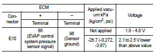
CAUTION: • Always calibrate the vacuum pump gauge when using it.
• Never apply below -93.3 kPa (-0.952 kg/cm2, -13.53 psi) or pressure over 101.3 kPa (1.033 kg/cm2, 14.69 psi).
Is the inspection result normal? YES >> INSPECTION END
NO >> Replace EVAP control system pressure sensor
 P0452 Evap control system pressure sensor
 P0455 Evap control system