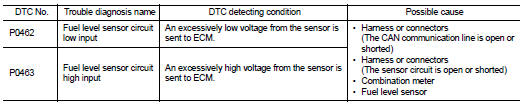
Nissan Altima (L32) 2007-2012 Service Manual: P0462, p0463 fuel level sensor
Description
The fuel level sensor is mounted in the fuel level sensor unit.
The sensor detects a fuel level in the fuel tank and transmits a signal to the combination meter. The combination meter sends the fuel level sensor signal to the ECM through CAN communication line.
It consists of two parts, one is mechanical float and the other is variable resistor. Fuel level sensor output voltage changes depending on the movement of the fuel mechanical float.
DTC Logic
DTC DETECTION LOGIC
NOTE: • If DTC P0462 or P0463 is displayed with DTC UXXXX, first perform the trouble diagnosis for DTC UXXXX.
• If DTC P0462 or P0463 is displayed with DTC P0607, first perform the trouble diagnosis for DTC P0607. Refer to EC-866, "DTC Logic".
This diagnosis indicates the former, to detect open or short circuit malfunction.
DTC CONFIRMATION PROCEDURE
1.PRECONDITIONING
If DTC Confirmation Procedure has been previously conducted, always turn ignition switch OFF and wait at least 10 seconds before conducting the next test.
TESTING CONDITION: Before performing the following procedure, confirm that battery voltage is between 11V and 16V at ignition switch ON.
>> GO TO 2.
2.PERFORM DTC CONFIRMATION PROCEDURE
1. Turn ignition switch ON and wait at least 5 seconds.
2. Check 1st trip DTC.
Is 1st trip DTC detected? YES >> Go to EC-851, "Diagnosis Procedure".
NO >> INSPECTION END
Diagnosis Procedure
1.CHECK COMBINATION METER FUNCTION
Refer to MWI-46, "Component Function Check".
Is the inspection result normal? YES >> GO TO 2.
NO >> Go to MWI-46, "Diagnosis Procedure"
2.CHECK INTERMITTENT INCIDENT
Refer to GI-42, "Intermittent Incident".
>> INSPECTION END
 P0461 fuel level sensor
 P0500 VSS