Nissan Altima (L32) 2007-2012 Service Manual: P0643 Sensor power supply
DTC Logic
DTC DETECTION LOGIC
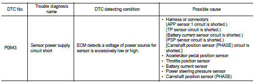
DTC CONFIRMATION PROCEDURE
1.PRECONDITIONING
If DTC Confirmation Procedure has been previously conducted, always turn ignition switch OFF and wait at least 10 seconds before conducting the next test.
TESTING CONDITION: Before performing the following procedure, confirm that battery voltage is more than 8V at idle.
>> GO TO 2.
2.PERFORM DTC CONFIRMATION PROCEDURE
1. Start engine and let it idle for 1 second.
2. Check DTC.
Is DTC detected? YES >> Go to EC-362, "Diagnosis Procedure".
NO >> INSPECTION END
Diagnosis Procedure
1.CHECK GROUND CONNECTION
1. Turn ignition switch OFF.
2. Check ground connection E9. Refer to Ground Inspection in GI-45, "Circuit Inspection".
Is the inspection result normal? YES >> GO TO 2.
NO >> Repair or replace ground connection.
2.CHECK ACCELERATOR PEDAL POSITION SENSOR 1 POWER SUPPLY CIRCUIT
1. Disconnect accelerator pedal position (APP) sensor harness connector.
2. Turn ignition switch ON.
3. Check the voltage between APP sensor harness connector and ground.
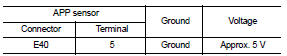
Is the inspection result normal? YES >> GO TO 7.
NO >> GO TO 3.
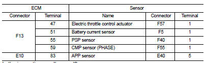
3.CHECK SENSOR POWER SUPPLY CIRCUITS
Check harness for short to power and short to ground, between the following terminals.
Is the inspection result normal? YES >> GO TO 4.
NO >> Repair short to ground or short to power in harness or connectors.
4.CHECK COMPONENTS
Check the following.
• Battery current sensor (Refer to EC-380, "Component Inspection".) • Power steering pressure sensor (Refer to EC-355, "Component Inspection".) • Camshaft position sensor (PHASE) (Refer to EC-284, "Component Inspection".) Is the inspection result normal? YES >> GO TO 5.
NO >> Replace malfunctioning component.
5.CHECK TP SENSOR
Refer to EC-191, "Component Inspection".
Is the inspection result normal? YES >> GO TO 9.
NO >> GO TO 6.
6.REPLACE ELECTRIC THROTTLE CONTROL ACTUATOR
1. Replace electric throttle control actuator.
2. Go to EC-29, "ACCELERATOR PEDAL RELEASED POSITION LEARNING : Special Repair Requirement".
>> INSPECTION END
7.CHECK APP SENSOR
Refer to EC-429, "Component Inspection".
Is the inspection result normal? YES >> GO TO 9.
NO >> GO TO 8.
8.REPLACE ACCELERATOR PEDAL ASSEMBLY
1. Replace accelerator pedal assembly.
2. Go to EC-29, "ACCELERATOR PEDAL RELEASED POSITION LEARNING : Special Repair Requirement".
>> INSPECTION END
9.CHECK INTERMITTENT INCIDENT
Refer to GI-42, "Intermittent Incident".
>> INSPECTION END
 P0607 ECM
 P0850 PNP Switch