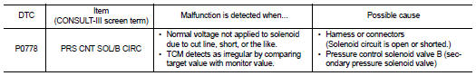
Nissan Altima (L32) 2007-2012 Service Manual: P0778 pressure control solenoid B electrical (sec pressure solenoid valve)
Description
The pressure control solenoid valve B (secondary pressure solenoid valve) regulates the oil pump discharge pressure to suit the driving condition in response to a signal sent from the TCM.
DTC Logic
DTC DETECTION LOGIC
DTC CONFIRMATION PROCEDURE
CAUTION: Always drive vehicle at a safe speed. NOTE: If “DTC CONFIRMATION PROCEDURE” has been previously performed, always turn ignition switch OFF.
Then wait at least 10 seconds before performing the next test.
1.CHECK DTC DETECTION

1. Start engine.
2. Drive vehicle and maintain the following conditions for at least 5 consecutive seconds.
3. Perform “SELF-DIAG RESULTS” mode for “TRANSMISSION”.

Follow the procedure “With CONSULT-III”.
Is “P0778 PRS CNT SOL/B CIRC” detected? YES >> Go to TM-336, "Diagnosis Procedure".
NO >> Check intermittent incident. Refer to GI-42, "Intermittent Incident".
Diagnosis Procedure
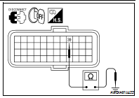
1.CHECK PRESSURE CONTROL SOLENOID VALVE B (SECONDARY PRESSURE SOLENOID VALVE) CIRCUIT
1. Turn ignition switch OFF.
2. Disconnect TCM harness connector.
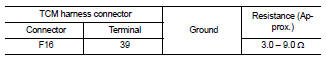
3. Check resistance between TCM harness connector F16 terminal 39 and ground.
Is the inspection result normal? YES >> GO TO 5.
NO >> GO TO 2.
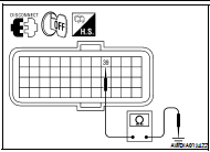
2.CHECK HARNESS BETWEEN TCM AND CVT UNIT [PRESSURE CONTROL SOLENOID VALVE B (SECONDARY PRESSURE SOLENOID VALVE)] (PART 1)
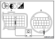
1. Disconnect CVT unit harness connector.
2. Check continuity between TCM harness connector F16 (A) terminal 39 and CVT unit harness connector F46 (B) terminal 3.
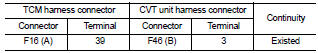
Is the inspection result normal? YES >> GO TO 3.
NO >> Repair or replace damaged parts.
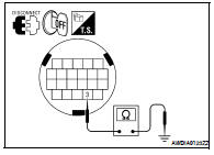
3.CHECK HARNESS BETWEEN TCM AND CVT UNIT [PRESSURE CONTROL SOLENOID VALVE B (SECONDARY PRESSURE SOLENOID VALVE)] (PART 2)
Check continuity between TCM harness connector F16 terminal 39 and ground.
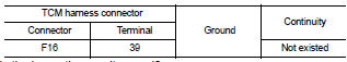
Is the inspection result normal? YES >> GO TO 4.
NO >> Repair or replace damaged parts.
4.CHECK PRESSURE CONTROL SOLENOID VALVE B (SECONDARY PRESSURE SOLENOID VALVE)
Check pressure control solenoid valve B (secondary pressure solenoid valve). Refer to TM-337, "Component Inspection [Pressure Control Solenoid Valve B (Secondary Pressure Solenoid Valve)]".
Is the inspection result normal? YES >> GO TO 5.
NO >> Replace transaxle assembly. Refer to TM-447, "Exploded View".
5.DETECT MALFUNCTIONING ITEMS
Check TCM connector pin terminals for damage or loose connection with harness connector.
Is the inspection result normal? YES >> Replace TCM. Refer to TM-430, "Exploded View".
NO >> Repair or replace damaged parts.
Component Inspection [Pressure Control Solenoid Valve B (Secondary Pressure Solenoid Valve)]
1.CHECK PRESSURE CONTROL SOLENOID VALVE B (SECONDARY PRESSURE SOLENOID VALVE)
Check resistance between CVT unit terminal 3 and ground.
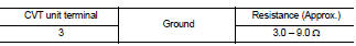
Is the inspection result normal? YES >> INSPECTION END
NO >> Replace transaxle assembly. Refer to TM-447, "Exploded View".
 P0776 pressure control solenoid B
performance (sec pressure solenoid
valve)
P0776 pressure control solenoid B
performance (sec pressure solenoid
valve) P0826 manual mode switch