Nissan Altima (L32) 2007-2012 Service Manual: P1572 ASCD Brake switch
Description
When the brake pedal is depressed, ASCD brake switch is turned OFF and stop lamp switch is turned ON.
ECM detects the state of the brake pedal by those two types of input (ON/OFF signal).
Refer to EC-1090, "System Diagram" for the ASCD function.
DTC Logic
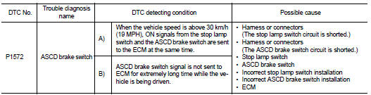
DTC DETECTION LOGIC
NOTE: • If DTC P1572 is displayed with DTC P0605, first perform the trouble diagnosis for DTC P0605. Refer to EC-1376, "DTC Logic".
• This self-diagnosis has the one trip detection logic. When malfunction A is detected, DTC is not stored in ECM memory. And in that case, 1st trip DTC and 1st trip freeze frame data are displayed.
1st trip DTC is erased when ignition switch is turned OFF. And even when malfunction A is detected in two consecutive trips, DTC is not stored in ECM memory.
DTC CONFIRMATION PROCEDURE
1.PRECONDITIONING
If DTC Confirmation Procedure has been previously conducted, always perform the following before conducting the next test.
1. Turn ignition switch OFF and wait at least 10 seconds.
2. Turn ignition switch ON.
3. Turn ignition switch OFF and wait at least 10 seconds.
NOTE: The procedure for malfunction B is not described. It takes an extremely long time to complete the procedure for malfunction B. By performing the procedure for malfunction A, the condition that causes malfunction B can be detected.
>> GO TO 2.
2.PERFORM DTC CONFIRMATION PROCEDURE

1. Start engine (ESP switch OFF).
2. Select “DATA MONITOR” mode with CONSULT-III.
3. Press MAIN switch and check that CRUISE lamp illuminate.
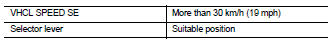
4. Drive the vehicle for at least 5 consecutive seconds under the following conditions.
CAUTION: Always drive vehicle at a safe speed.
NOTE: This procedure may be conducted with the drive wheels lifted in the shop or by driving the vehicle.
If a road test is expected to be easier, it is unnecessary to lift the vehicle.
5. Check 1st trip DTC.

Follow the procedure “With CONSULT-III” above.
Is 1st trip DTC detected? YES >> Go to EC-1414, "Diagnosis Procedure".
NO >> GO TO 3.
3.PERFORM DTC CONFIRMATION PROCEDURE

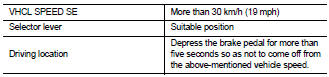
1. Drive the vehicle for at least 5 consecutive seconds under the following conditions.
CAUTION: Always drive vehicle at a safe speed.
NOTE: This procedure may be conducted with the drive wheels lifted in the shop or by driving the vehicle.
If a road test is expected to be easier, it is unnecessary to lift the vehicle.
2. Check 1st trip DTC.

Follow the procedure “With CONSULT-III” above.
Is 1st trip DTC detected? YES >> Go to EC-1414, "Diagnosis Procedure".
NO >> INSPECTION END
Diagnosis Procedure
1.CHECK OVERALL FUNCTION-I

1. Turn ignition switch ON.
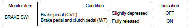
2. Select “BRAKE SW1” in “DATA MONITOR” mode with CONSULT-III.
3. Check “BRAKE SW1” indication under the following conditions.

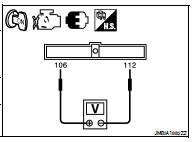
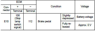
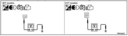
1. Turn ignition switch ON.
2. Check the voltage between ECM harness connectors.
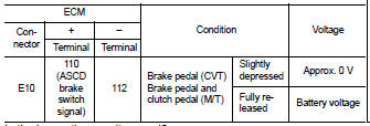
Is the inspection result normal? YES >> GO TO 2.
NO-1 >> CVT models: GO TO 3.
NO-2 >> M/T models: GO TO 7.
2.CHECK OVERALL FUNCTION-II

Check “BRAKE SW2” indication in “DATA MONITOR” mode.
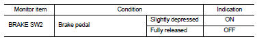

Check the voltage between ECM harness connectors.
Is the inspection result normal? YES >> GO TO 19.
NO >> GO TO 15.
3.CHECK ASCD BRAKE SWITCH POWER SUPPLY CIRCUIT
1. Turn ignition switch OFF.
2. Disconnect ASCD brake switch harness connector.
3. Turn ignition switch ON.
4. Check the voltage between ASCD brake switch harness connector and ground.
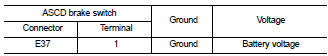
Is the inspection result normal? YES >> GO TO 5.
NO >> GO TO 4.
4.DETECT MALFUNCTIONING PART
Check the following.
• Fuse block (J/B) connector E6
• 10 A fuse (No. 3) • Harness for open or short between ASCD brake switch and fuse
>> Repair open circuit, short to ground or short to power in harness or connectors.
5.CHECK ASCD BRAKE SWITCH INPUT SIGNAL CIRCUIT FOR OPEN AND SHORT
1. Turn ignition switch OFF.
2. Disconnect ECM harness connector.
3. Check the continuity between ASCD brake switch harness connector and ECM harness connector.
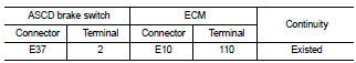
4. Also check harness for short to ground and short to power.
Is the inspection result normal? YES >> GO TO 6.
NO >> Repair open circuit, short to ground or short to power in harness or connectors.
6.CHECK ASCD BRAKE SWITCH
Refer to EC-1418, "Component Inspection (ASCD Brake Switch)".
Is the inspection result normal? YES >> GO TO 19.
NO >> Replace ASCD brake switch.
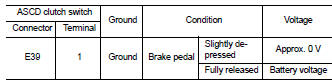
7.CHECK ASCD BRAKE SWITCH CIRCUIT
1. Turn ignition switch OFF.
2. Disconnect ASCD clutch switch harness connector.
3. Turn ignition switch ON.
4. Check the voltage between ASCD clutch switch harness connector and ground.
Is the inspection result normal? YES >> GO TO 12.
NO >> GO TO 8.
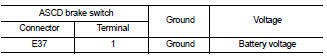
8.CHECK ASCD BRAKE SWITCH POWER SUPPLY CIRCUIT
1. Turn ignition switch OFF.
2. Disconnect ASCD brake switch harness connector.
3. Turn ignition switch ON.
4. Check the voltage between ASCD brake switch harness connector and ground.
Is the inspection result normal? YES >> GO TO 10.
NO >> GO TO 9.
9.DETECT MALFUNCTIONING PART
Check the following.
• Fuse block (J/B) connector E6
• 10 A fuse (No. 3) • Harness for open or short between ASCD brake switch and fuse
>> Repair open circuit, short to ground or short to power in harness or connectors.
10.CHECK ASCD BRAKE SWITCH INPUT SIGNAL CIRCUIT FOR OPEN AND SHORT
1. Turn ignition switch OFF.
2. Check the continuity between ASCD brake switch harness connector and ASCD clutch switch harness connector.
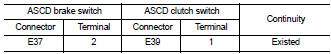
Is the inspection result normal? YES >> GO TO 11.
NO >> Repair open circuit, short to ground or short to power in harness or connectors.
11.CHECK ASCD BRAKE SWITCH
Refer to EC-1418, "Component Inspection (ASCD Brake Switch)".
Is the inspection result normal? YES >> GO TO 19.
NO >> Replace ASCD brake switch.
12.CHECK ASCD BRAKE SWITCH INPUT SIGNAL CIRCUIT FOR OPEN AND SHORT
1. Turn ignition switch OFF.
2. Disconnect ECM harness connector.
3. Check the continuity between ASCD clutch switch harness connector and ECM harness connector.
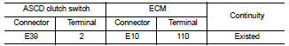
4. Also check harness for short to ground and short to power.
Is the inspection result normal? YES >> GO TO 14.
NO >> GO TO 13.
13.DETECT MALFUNCTIONING PART
Check the following.
• Junction block connectors E45, E46
• Joint connector-E06 E27
• Harness for open or short between ASCD clutch switch and ECM
>> Repair open circuit, short to ground or short to power in harness or connectors.
14.CHECK ASCD CLUTCH SWITCH
Refer to EC-1419, "Component Inspection (ASCD Clutch Switch)".
Is the inspection result normal? YES >> GO TO 19.
NO >> Replace ASCD clutch switch.
15.CHECK STOP LAMP SWITCH POWER SUPPLY CIRCUIT
1. Turn ignition switch OFF.
2. Disconnect stop lamp switch harness connector.
3. Check the voltage between stop lamp switch harness connector and ground.
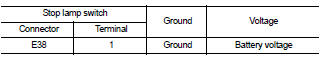
Is the inspection result normal? YES >> GO TO 17.
NO >> GO TO 16.
16.DETECT MALFUNCTIONING PART
Check the following.
• Fuse block (J/B) connector E6
• 10 A fuse (No. 7) • Harness for open or short between stop lamp switch and battery
>> Repair open circuit, short to ground or short to power in harness or connectors.
17.CHECK STOP LAMP SWITCH INPUT SIGNAL CIRCUIT FOR OPEN AND SHORT
1. Disconnect ECM harness connector.
2. Check the continuity between stop lamp switch harness connector and ECM harness connector.
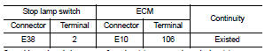
3. Also check harness for short to ground and short to power.
Is the inspection result normal? YES >> GO TO 18.
NO >> Repair open circuit, short to ground or short to power in harness or connectors.
18.CHECK STOP LAMP SWITCH
Refer to EC-1420, "Component Inspection (Stop Lamp Switch)" Is the inspection result normal? YES >> GO TO 19.
NO >> Replace stop lamp switch.
19.CHECK INTERMITTENT INCIDENT
Refer to GI-42, "Intermittent Incident".
>> INSPECTION END
Component Inspection (ASCD Brake Switch)
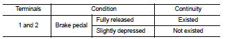
1.CHECK ASCD BRAKE SWITCH-I
1. Turn ignition switch OFF.
2. Disconnect ASCD brake switch harness connector.
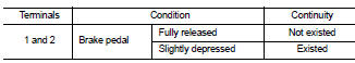
3. Check the continuity between ASCD brake switch terminals under the following conditions.
Is the inspection result normal? YES >> INSPECTION END
NO >> GO TO 2.
2.CHECK ASCD BRAKE SWITCH-II
1. Adjust ASCD brake switch installation. Refer to BR-13, "Inspection and Adjustment".
2. Check the continuity between ASCD brake switch terminals under the following conditions.
Is the inspection result normal? YES >> INSPECTION END
NO >> Replace ASCD brake switch.
Component Inspection (ASCD Clutch Switch)
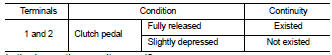
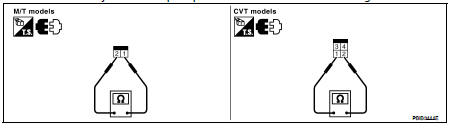
1.CHECK ASCD CLUTCH SWITCH-I
1. Turn ignition switch OFF.
2. Disconnect ASCD clutch switch harness connector.
3. Check harness continuity between ASCD clutch switch terminals under the following conditions.
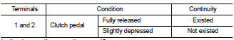
Is the inspection result normal? YES >> INSPECTION END
NO >> GO TO 2.
2.CHECK ASCD CLUTCH SWITCH-II
1. Adjust ASCD clutch switch installation. Refer to BR-13, "Inspection and Adjustment".
2. Check harness continuity between ASCD clutch switch terminals under the following conditions.
Is the inspection result normal? YES >> INSPECTION END
NO >> Replace ASCD clutch switch.
Component Inspection (Stop Lamp Switch)
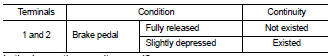
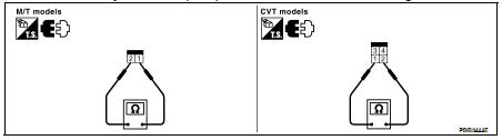
1.CHECK STOP LAMP SWITCH-I
1. Turn ignition switch OFF.
2. Disconnect stop lamp switch harness connector.
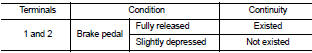
3. Check harness continuity between stop lamp switch terminals under the following conditions.
Is the inspection result normal? YES >> INSPECTION END
NO >> GO TO 2.
2.CHECK STOP LAMP SWITCH-II
1. Adjust stop lamp switch installation. Refer to BR-13, "Inspection and Adjustment".
2. Check harness continuity between stop lamp switch terminals under the following conditions.
Is the inspection result normal? YES >> INSPECTION END
NO >> Replace stop lamp switch.
 P1564 ASCD Steering switch
 P1574 ASCD Vehicle speed sensor