Nissan Altima (L32) 2007-2012 Service Manual: P1715 input speed sensor (primary speed sensor)
Description
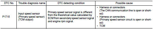
ECM receives primary speed sensor signal from TCM through CAN communication line. ECM uses this signal for engine control.
DTC Logic
DTC DETECTION LOGIC NOTE: • If DTC P1715 is displayed with DTC UXXXX, first perform the trouble diagnosis for DTC U1000,XXXX.
• If DTC P1715 is displayed with DTC P0335, first perform the trouble diagnosis for DTC P0335. Refer to EC-783, "DTC Logic".
• If DTC P1715 is displayed with DTC P0340, first perform the trouble diagnosis for DTC P0340. Refer to EC-787, "DTC Logic".
• If DTC P1715 is displayed with DTC P0605, first perform the trouble diagnosis for DTC P0605. Refer to EC-864, "DTC Logic".
• If DTC P1715 is displayed with DTC P0607, first perform the trouble diagnosis for DTC P0607. Refer to EC-866, "DTC Logic".
DTC CONFIRMATION PROCEDURE
1.PRECONDITIONING
If DTC Confirmation Procedure has been previously conducted, always turn ignition switch OFF and wait at least 10 seconds before conducting the next test.
>> GO TO 2.
2.PERFORM DTC CONFIRMATION PROCEDURE
1. Start engine and drive the vehicle at more than 50 km/h (31 MPH) for at least 5 seconds.
CAUTION: Always drive vehicle at a safe speed.
2. Check 1st trip DTC.
Is 1st trip DTC detected? YES >> Go to EC-909, "Diagnosis Procedure".
NO >> INSPECTION END
Diagnosis Procedure
1.CHECK DTC WITH TCM
Check DTC with TCM. Refer to TM-296, "Diagnosis Description".
Is the inspection result normal? YES >> GO TO 2.
NO >> Perform trouble shooting relevant to DTC indicated.
2.REPLACE TCM
Replace TCM.
>> INSPECTION END
 P1574 ASCD Vehicle speed sensor
 P1805 brake switch