Nissan Altima (L32) 2007-2012 Service Manual: P1801 Vias control solenoid valve 2
Description
The VIAS control solenoid valve 2 cuts the intake manifold vacuum signal for power valve 2 control. It responds to ON/OFF signals from the ECM. When the solenoid is OFF, the vacuum signal from the intake manifold is cut. When the ECM sends an ON signal the coil pulls the plunger downward and sends the vacuum signal to the power valve actuator 2.
DTC Logic
DTC DETECTION LOGIC
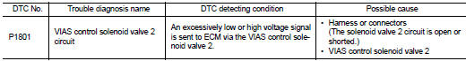
DTC CONFIRMATION PROCEDURE
1.CONDITIONING
If DTC Confirmation Procedure has been previously conducted, always perform the following before conducting the next test.
1. Turn ignition switch OFF and wait at least 10 seconds.
2. Turn ignition switch ON.
3. Turn ignition switch OFF and wait at least 10 seconds.
TESTING CONDITION: Before performing the following procedure, confirm battery voltage is more than 11 V at idle.
>> GO TO 2.
2.PERFORM DTC CONFIRMATION PROCEDURE
1. Start engine and let it idle for at least 5 seconds.
2. Check 1st trip DTC.
Is 1st trip DTC detected? YES >> Go to EC-1431, "Diagnosis Procedure".
NO >> INSPECTION END
Diagnosis Procedure
1.CHECK VIAS CONTROL SOLENOID VALVE 2 POWER SUPPLY CIRCUIT
1. Turn ignition switch OFF.
2. Disconnect VIAS control solenoid valve 2 harness connector.
3. Turn ignition switch ON.
4. Check the voltage between VIAS control solenoid valve 2 harness connector and ground.
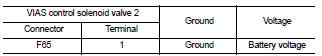
Is the inspection result normal? YES >> GO TO 2.
NO >> Repair open circuit, short to ground or short to power in harness or connectors.
2.CHECK VIAS CONTROL SOLENOID VALVE 2 OUTPUT SIGNAL CIRCUIT FOR OPEN AND SHORT
1. Turn ignition switch OFF.
2. Disconnect ECM harness connector.
3. Check the continuity between VIAS control solenoid valve 2 harness connector and ECM harness connector.
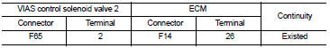
4. Also check harness for short to ground and short to power.
Is the inspection result normal? YES >> GO TO 3.
NO >> Repair open circuit, short to ground or short to power in harness or connectors.
3.CHECK VIAS CONTROL SOLENOID VALVE 2
Refer to EC-1432, "Component Inspection".
Is the inspection result normal? YES >> GO TO 4.
NO >> Replace VIAS control solenoid valve 2.
4.CHECK INTERMITTENT INCIDENT
Refer to GI-42, "Intermittent Incident".
>> INSPECTION END
Component Inspection
1.CHECK VIAS CONTROL SOLENOID VALVE 2

1. Turn ignition switch OFF.
2. Reconnect all harness connectors disconnected.
3. Disconnect vacuum hoses connected to VIAS control solenoid valve 2.
4. Turn ignition switch ON.
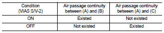
5. Select “VIAS S/V-2” in “ACTIVE TEST” mode with CONSULT-III.
6. Check air passage continuity and operation delay time under the following conditions.
1. Turn ignition switch OFF.
2. Disconnect VIAS control solenoid valve 2 harness connector.
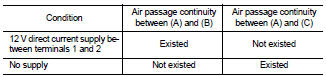
3. Disconnect vacuum hoses connected to VIAS volume control solenoid valve 2.
4. Check air passage continuity and operation delay time under the following conditions.

Is the inspection result normal? YES >> INSPECTION END
NO >> Replace VIAS control solenoid valve 2
 P1800 Vias control solenoid valve 1
 P1805 Brake switch