Nissan Altima (L32) 2007-2012 Service Manual: Power supply and ground circuit for front air control
Description
COMPONENT DESCRIPTION
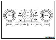
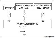
FRONT AIR CONTROL
The front air control has a built-in microcomputer which processes information sent from various sensors needed for air conditioner operation. The air mix door motors, mode door motor, intake door motor, blower motor and compressor are then controlled.
Signals from various switches and Potentio Temperature Control (PTC) are directly entered into front air control.
POTENTIO TEMPERATURE CONTROL (PTC)
The PTC is built into the front air control.
Component Function Check
COMPONENT INSPECTION
SYMPTOM: A/C system does not come on.
INSPECTION FLOW
1. CONFIRM SYMPTOM BY PERFORMING OPERATION CHECK - AUTO MODE
1. Press AUTO switch (indicator should illuminate).
2. Confirm that the compressor clutch engages (sound or visual inspection). (Discharge air and blower speed will depend on ambient, in-vehicle and set temperature.) Can a symptom be duplicated? YES >> GO TO 3
NO >> GO TO 2
2. PERFORM COMPLETE OPERATIONAL CHECK
Perform a complete operational check and check for any symptoms. Refer to HAC-5, "Description and Conditions".
Is the inspection result normal? YES >> Refer to HAC-83, "Symptom Matrix Chart".
NO >> System OK.
3. CHECK FOR SERVICE BULLETINS
Check for any service bulletins.
>> GO TO 4
4. CHECK MAIN POWER SUPPLY AND GROUND CIRCUIT
Check main power supply and ground circuit. Refer to HAC-61, "Diagnosis Procedure".
Is the inspection result normal? YES >> Replace front air control. Refer to VTL-8, "Removal and Installation".
NO >> Repair as necessary.
Diagnosis Procedure
DIAGNOSIS PROCEDURE FOR A/C SYSTEM
SYMPTOM: A/C system does not come on.
1.CHECK POWER SUPPLY CIRCUIT FOR FRONT AIR CONTROL
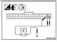
1. Disconnect front air control connector M37.
2. Press ignition switch ON.
3. Check voltage between front air control connector M37 terminals 19, 39 and 40, and ground.
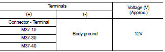
Is the inspection result normal? YES >> GO TO 2
NO >> Check the following.
• 10A fuses [Nos. 6, 19, and 3, located in the fuse block (J/B)].
• If fuses are OK, check for open circuit in wiring harness. Repair or replace as necessary.
• If fuses are NG, replace fuse and check wiring harness for short circuit. Repair or replace as necessary.
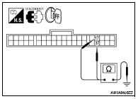
2.CHECK BODY GROUND CIRCUIT FOR FRONT AIR CONTROL
1. Press ignition switch OFF.
2. Check continuity between front air control connector M37 terminals 17and 37 and ground.
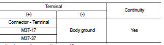
Is the inspection result normal? YES >> • Replace front air control. Refer to VTL-8, "Removal and Installation".
• Inspection End.
NO >> Repair or replace harness.
 Intake sensor
 ECU diagnosis