Nissan Altima (L32) 2007-2012 Service Manual: Power window system
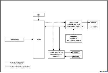
System Diagram
POWER WINDOW ANTI-PINCH SYSTEM
System Description
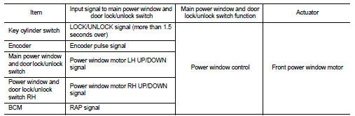
POWER WINDOW MAIN SWITCH
INPUT/OUTPUT SIGNAL CHART
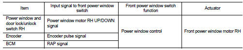
POWER WINDOW AND DOOR LOCK/UNLOCK SWITCH
INPUT/OUTPUT SIGNAL CHART
POWER WINDOW OPERATION
• Power window system is operable during the retained power operation timer after turning ignition switch ON and OFF.
• Main power window and door lock/unlock switch can open/close all windows.
• Power window and door lock unlock switch RH can open/close the corresponding window.
POWER WINDOW AUTO-OPERATION (LH & RH)
• AUTO UP/DOWN operation can be performed when main power window and door lock/unlock switch & power window and door lock/unlock switch RH turns to AUTO.
• Encoder continues detecting the movement of power window motor and transmits to power window switch as the encoder pulse signal while power window motor is operating.
• Power window switch reads the changes of encoder signal and stops AUTO operation when door glass is at fully opened/closed position.
• Power window motor is operable in case encoder is malfunctioning.
RETAINED POWER OPERATION
• Retained power operation is an additional power supply function that enables power window system to operate during the 45 seconds even when ignition switch is turned OFF
Retained power function cancel conditions
• Door CLOSE (door switch OFF)→OPEN (door switch ON).
• When ignition switch is ON.
• When timer time passes. (45 seconds)
POWER WINDOW LOCK
Ground circuit inside main power window and door lock/unlock switch shuts off when power window lock switch is ON. This inhibits power window switch operation except with the main power window and door lock/ unlock switch.
ANTI-PINCH OPERATION (LH & RH)
• Pinch foreign material in the door glass during AUTO-UP operation, and it is the anti-pinch function that lowers the door glass 150 mm or 2 seconds when detected.
• Encoder continues detecting the movement of power window motor and transmits to power window switch as the encoder pulse signal while power window motor is operating.
• Resistance is applied to the power window motor rotation that changes the frequency of encoder pulse signal if foreign material is trapped in the door glass.
• Power window switch controls to lower the window glass for 150 mm or 2 seconds after it detects encoder pulse signal frequency change.
OPERATION CONDITION
• When all door glass AUTO-UP operation is performed (anti-pinch function does not operate just before the door glass closes and is fully closed) NOTE: Depending on environment and driving conditions, if a similar impact or load is applied to the door glass, it may lower.
KEY CYLINDER SWITCH OPERATION
Hold the door key cylinder to the LOCK or UNLOCK direction for more than 1 second to OPEN or CLOSE front power windows when ignition switch is OFF. In addition, it stops when key position is moved to NEUTRAL when operating.
OPERATION CONDITION
• Ignition switch OFF
• Hold door key cylinder to LOCK position for more than 1 second to perform CLOSE operation of the door glass.
• Hold door key cylinder to UNLOCK position for more than 1 second to perform OPEN operation of the door glass.
KEYLESS POWER WINDOW DOWN OPERATION (LH & RH)
Front power windows open when the unlock button on Intelligent Key is activated and kept pressed for more than 3(NOTE) seconds with the ignition switch OFF. The windows keep opening if the unlock button is continuously pressed.
The power window opening stops when the following operations are performed: • When the unlock button is kept pressed more than 15 seconds.
• When the ignition switch is turned ON while the power window opening is operated.
• When the unlock button is released.
While retained power operation activate, keyless power window down function cannot be operated.
NOTE: Keyless power window down operation mode can be changed by “PW DOWN SET” mode in “WORK SUPPORT”.
Refer to BCS-18, "COMMON ITEM : CONSULT-III Function".
NOTE: Use CONSULT-III to change settings.
MODE 1 (3sec) / MODE 2 (OFF) / MODE 3 (5sec)
Component Parts Location

1. BCM M16, M17, M18, M19 (view with instrument panel removed)
2. Door lock assembly LH (key cylinder switch) D10
3. Power window motor LH D9, RH D104
4. Main power window and door lock/ unlock switch D7
5. Power window and door lock/unlock switch RH D105
6. Front door switch LH B8, RH B108
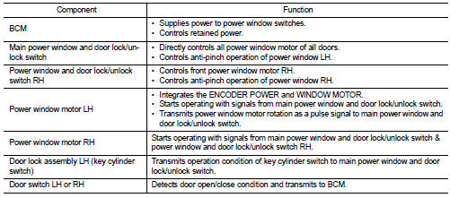
Component Description
POWER WINDOW ANTI-PINCH SYSTEM
 Function diagnosis
 Diagnosis system (BCM)