Nissan Altima (L32) 2007-2012 Service Manual: Refrigeration system
Component
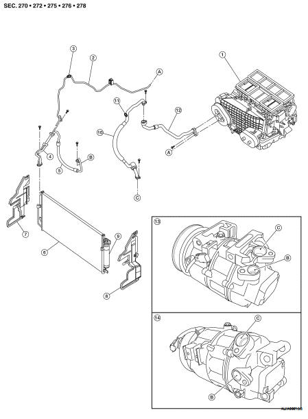
1. Heater and cooling unit assembly
2. High-pressure pipe
3. High-pressure A/C service valve
4. Junction pipe
5. High-pressure flexible hose
6. Condenser and liquid tank
7. Air deflector RH (QR25DE shown, VQ35DE similar)
8. Air deflector LH (QR25DE shown, VQ35DE similar)
9. Refrigerant pressure sensor
10. Low-pressure flexible hose
11. Low-pressure A/C service valve
12. Low-pressure pipe
13. Compreesor (QR25DE)
14. Compressor (VQ35DE)
A. High-pressure pipe to heater and cooling unit assembly
B. high-pressure flexible hose to compressor
C. low-pressure flexible hose to compressor
NOTE: Refer to HA-5, "Precaution for Refrigerant Connection".
HFC-134a (R-134a) Service Procedure
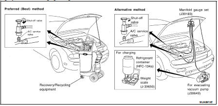
SETTING OF SERVICE TOOLS AND EQUIPMENT
WARNING: Avoid breathing the A/C refrigerant and oil vapor or mist. Exposure may irritate eyes, nose, and throat.
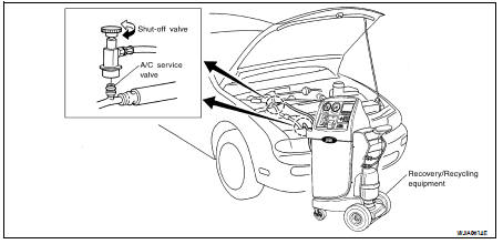
Remove the HFC-134a (R-134a) from the A/C system using certified service equipment meeting the requirements of SAE J2210 (R-134a recycling equipment) or SAE J2201 (R-134a recovery equipment).
If an accidental system discharge occurs, ventilate the work area before resuming service. Additional health and safety information may be obtained from the refrigerant and oil manufacturers.
Discharging Refrigerant
Evacuating System and Charging Refrigerant
Discharging, Evacuating, and Recharging the A/C System
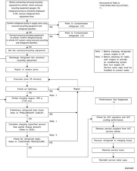
*1 HA-21, "Maintenance of Oil Quantity in Compressor"
*2 HA-25, "Checking of Refrigerant Leaks"
*3 HA-25, "Checking of Refrigerant Leaks"
*4 HAC-5, "Operational Check"
*5 HA-4, "Contaminated Refrigerant"
 On-vehicle repair
 Compressor