Nissan Altima (L32) 2007-2012 Service Manual: Signal buffer system
System Diagram
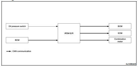
System Description
• IPDM E/R reads the status of the oil pressure switch and transmits the oil
pressure switch signal to BCM via
CAN communication. Refer to PCS-11, "System Description".
• IPDM E/R receives the rear window defogger status signal from BCM via CAN
communication and transmits
it to ECM via CAN communication. Refer to PCS-11, "System Description".
System Diagram
System Description
COOLING FAN CONTROL
IPDM E/R controls cooling fans according to the status of the cooling fan
speed request signal received from
ECM via CAN communication. R ...
System Diagram
System Description
OUTLINE
• IPDM E/R incorporates a power consumption control function that reduces the
power consumption according
to the vehicle status.
• IPDM E/R ch ...
 Power control system
 Power consumption control system