Nissan Altima (L32) 2007-2012 Service Manual: Tachometer
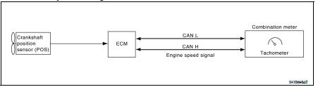
System Diagram
System Description
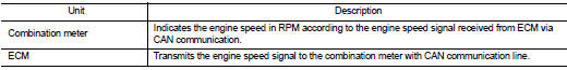
The tachometer indicates engine speed in revolutions per minute (rpm).
The ECM provides an engine speed signal to the combination meter via CAN
communication lines.
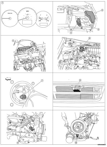
Component Parts Location
1. Combination meter M24
2. IPDM E/R E17, E18, E201, F10
3. ECM E10
4. TCM F16
5. BCM M17, M18, M19, M21 (view with
instrument panel removed)
6. ABS actuator and electric unit (control
unit) E26
7. Fuel level sensor unit and fuel pump
(fuel level sensor) B42 (view with rear
seat and inspection hole cover removed)
8. Ambient sensor E211 (view of front
bumper fascia)
9. Oil pressure switch F41 (QR25DE)
(view with engine removed)
10. Oil pressure switch F41 (VQ35DE)
(view with engine removed)
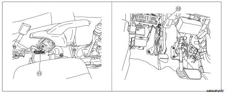
11. Parking brake switch M73
(Sedan with M/T and Coupe)
(view with center console removed)
12. Parking brake switch E35
(Sedan with CVT)
(view with instrument lower cover LH
removed)
Component Description
System Diagram
System Description
The ABS actuator and electric unit (control unit) provides a vehicle speed
signal to the combination meter via
CAN communication lines.
Component Parts Locat ...
System Diagram
System Description
The engine coolant temperature gauge indicates the engine coolant
temperature.
The ECM provides an engine coolant temperature signal to the combination mete ...
Other materials: Warning/Indicator lights
Warning/Indicator light (red)
Brake warning
light
Charge warning
light
Electronic parking
brake indicator
light (if so
equipped)
Engine oil pressure
warning light
Master warning
light
Seat belt warning
light and chime
Security indicator
light
Supplemental air
bag warning light
Warning/Indicator
ligh ...
Warning/Indicator lights (yellow)
For additional information on warnings
and indicators, see "Vehicle information
display-5 inch (13 cm) Type A" or
"Vehicle information display-7 inch (18 cm)
Type B".
or
Anti-lock Braking
System (ABS)
warning light
When the ignition switch is placed in the ON
position, the ABS warning light illumi ...
NISSAN Advanced Air Bag System
Top tether strap anchor
Roof-mounted curtain side-impact and
rollover supplemental air bag inflators
Rear seat belts
Roof-mounted curtain side-impact and
rollover supplemental air bag
Front seat-mounted side-impact supplemental
air bag
Head restraints/headrests
Front seat belts
Side-imp ...
 Speedometer
 Engine coolant temperature gauge