Nissan Altima (L32) 2007-2012 Service Manual: Transaxle assembly
Exploded View
CASE AND HOUSING
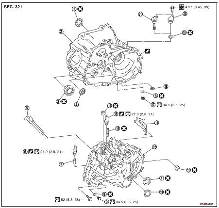
1. Differential side oil seal
2. Clutch housing
3. Input shaft oil seal
4. Oil channel
5. Oil gutter A
6. Back-up lamp switch
7. Plunger
8. Gasket
9. Plug
10. Bore plug
11. Striking rod oil seal
12. Transaxle case
13. Oil gutter B
14. Air breather tube
15. Park/Neutral position (PNP) switch
16. Shifter lever oil seal
17. Drain plug
18. Magnet
19. O-ring
20. Filler plug (With ABS models)
21. Speedometer pinion gear (Without ABS models)

SHAFT AND GEAR
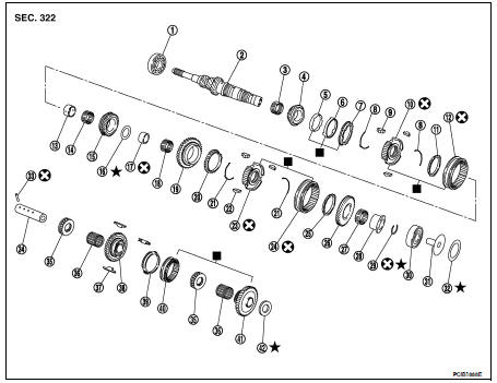
1. Input shaft front bearing
2. Input shaft
3. 3rd needle bearing
4. 3rd input gear
5. 3rd inner baulk ring
6. 3rd synchronizer cone
7. 3rd outer baulk ring
8. 3rd-4th spread spring
9. 3rd-4th shifting insert
10. 3rd-4th synchronizer hub
11. 4th baulk ring
12. 3rd-4th coupling sleeve
13. 4th input gear bushing
14. 4th needle bearing
15. 4th input gear
16. Thrust washer
17. 5th input gear bushing
18. 5th needle bearing
19. 5th input gear
20. 5th baulk ring
21. 5th-6th spread spring
22. 5th-6th shifting insert
23. 5th-6th synchronizer hub
24. 5th-6th coupling sleeve
25. 6th baulk ring
26. 6th input gear
27. 6th needle bearing
28. 6th input gear bushing
29. Snap ring
30. Input shaft rear bearing
31. Oil channel
32. Input shaft rear bearing adjusting shim
33. Retaining pin
34. Reverse idler shaft
35. Thrust needle bearing35. Thrust needle bearing
36. Reverse idler gear needle bearing
37. Reverse insert spring
38. Reverse idler gear (Front)
39. Reverse baulk ring
40. Reverse coupling sleeve
41. Reverse idler gear (Rear)
42. Reverse idler gear adjusting shim
 Replace the parts as a set.
Refer to GI-4, "Components" for symbols not described on the above.
• Apply gear oil to gears, shafts, synchronizers, and bearings when assembly.
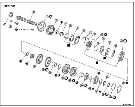
1. Mainshaft front bearing
2. Mainshaft bearing retainer
3. Mainshaft
4. Reverse main gear
5. 1st main gear
6. 1st main gear bushing
7. 1st needle bearing
8. 1st inner baulk ring
9. 1st synchronizer cone
10. 1st outer baulk ring
11. 1st-2nd spread spring
12. 1st-2nd shifting insert
13. 1st-2nd synchronizer hub
14. 2nd outer baulk ring
15. 2nd synchronizer cone
16. 2nd inner baulk ring
17. 1st-2nd coupling sleeve
18. 2nd main gear bushing
19. 2nd needle bearing
20. 2nd main gear
21. 3rd main gear
22. 3rd-4th mainshaft spacer
23. 4th main adjusting shim
24. 4th main gear
25. 5th main gear
26. 5th-6th mainshaft spacer
27. 6th main gear
28. 6th main gear adjusting shim
29. Mainshaft rear bearing
30. Mainshaft C-ring
31. C-ring holder
32. Snap ring
32. Snap ring
 Replace the parts as a set.
Refer to GI-4, "Components" for symbols not described on the above.
• Apply gear oil to gears, shafts, synchronizers, and bearings when assembly.
SHIFT FORK AND FORK ROD
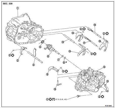
1. Clutch housing
2. Retaining pin
3. Reverse shift fork
4. Reverse fork rod
5. Return spring
6. Striking rod assembly
7. Striking rod shim
8. Striking rod adjusting shim
9. Shifter lever A
10. Shifter lever B
11. Guide bolt
12. Selector lever
13. Transaxle case
14. 3rd-4th shift fork
15. 3rd-4th fork rod
16. 1st-2nd shift fork
17. 1st-2nd fork rod
18. 5th-6th shift fork
19. 5th-6th fork rod
FINAL DRIVE
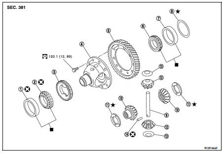
1. Differential side bearing outer race (clutch housing side)
2. Differential side bearing (clutch housing side)
3. Speedometer drive gear
4. Differential case
5. Final gear
6. Differential side bearing (transaxle case side)
7. Differential side bearing outer race (transaxle case side)
8. Differential side bearing adjusting shim
9. Pinion mate shaft
10. Side gear
11. Side gear thrust washer
12. Pinion mate gear
13. Pinion mate thrust washer
14. Retaining pin
■ Replace parts as a set
Disassembly
1. Remove drain plug and gasket from clutch housing.
2. Remove plug bolt and then plug (with ABS models) or speedometer pinion gear (without ABS models) and O-ring from clutch housing.
3. Remove plug and gasket from transaxle case.
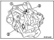
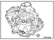
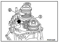
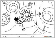
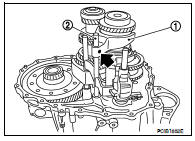
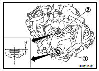
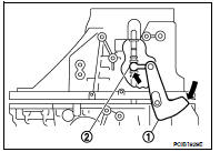
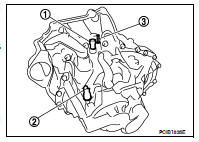
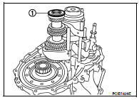
4. Remove park/neutral position (PNP) switch (1) from transaxle case.
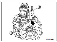
5. Remove back-up lamp switch (2) and plunger from transaxle case.
CAUTION: Do not lose plunger.
6. Remove air breather tube (3) from transaxle case.
7. Remove guide bolt from transaxle case.
8. Remove retaining pin using suitable tool and then remove selector lever from transaxle case.
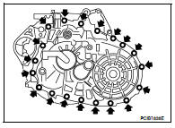
9. Remove transaxle case bolts.
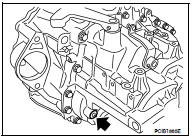
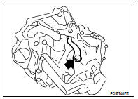
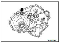
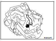
10. Remove bore plug from transaxle case. CAUTION: • Do not damage transaxle case.
• Access bore plug from cutout (A) of transaxle case when removing.
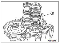
11. Remove transaxle case following the procedures below.
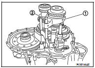
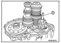
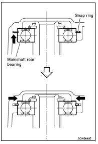
a. Expand snap ring at mainshaft rear bearing accessing from the bore plug hole. Then pull up transaxle case from clutch housing until snap ring comes off.
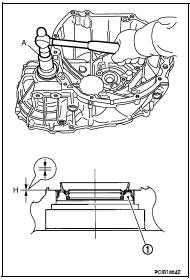
b. With shifter lever A (1) held in the position shown, remove transaxle case from clutch housing.
CAUTION: Do not drop each adjusting shim.
NOTE: Make sure to hold shifter lever A (1) in the position shown. Otherwise transaxle case cannot be removed from clutch housing.
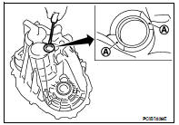
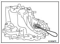
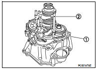
12. Remove oil gutter A (1) and oil gutter B (2) from transaxle case.
A : Tab of oil gutter
13. Remove snap ring from transaxle case.

14. Remove retaining pin using suitable tool and then remove shifter lever A and shifter lever B from transaxle case.
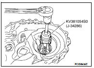
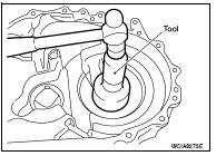
15. Remove differential side bearing outer race from transaxle case using Tool, then remove differential side bearing adjusting shim from transaxle case.
Tool number :KV381054SO (J-34286)
CAUTION: Do not damage transaxle case.
16. Remove differential side oil seal from transaxle case using suitable tool.
CAUTION: Do not damage transaxle case.
17. Remove shifter lever oil seal (1) and striking rod oil seal (2) from transaxle case.
CAUTION: Do not damage transaxle case.
18. Remove striking rod shim (1), striking rod adjusting shim (2), mainshaft rear bearing adjusting shim (3), input shaft rear bearing adjusting shim (4), and reverse idler gear adjusting shim (5).
19. Remove retaining pin of reverse shift fork (1) using suitable tool.
2 : Reverse fork rod

20. Rotate striking lever of striking rod assembly as shown. Then rotate reverse fork rod to a position where bracket of reverse fork rod does not interfere with striking lever of striking rod assembly.
21. Pull out reverse shift fork and reverse fork rod.
22. Remove retaining pin of 5th-6th shift fork (1) using suitable tool.
2 : 5th-6th fork rod
25. Pull out 5th-6th shift fork (1) and 5th-6th fork rod (2).
26. Pull out 3rd-4th shift fork (1).
27. Remove retaining pin of 1st-2nd shift fork (1) using suitable tool.
28. Pull out 1st-2nd shift fork and 1st-2nd fork rod (2).
29. Remove striking rod assembly (1).
30. Remove gear components from clutch housing in the following procedure.
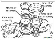
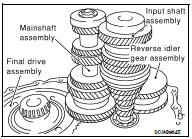
a. Remove a set of input shaft assembly, mainshaft assembly, and reverse idler gear assembly by tapping the tip of input shaft from the back of the clutch housing with a plastic hammer.
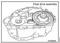
CAUTION: Always withdraw mainshaft straight out. Failure to do so can damage resin oil channel on clutch housing side. b. Remove final drive assembly.
31. Remove magnet from clutch housing.
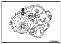
32. Remove mainshaft bearing retainer and then mainshaft front bearing from clutch housing using Tool.
Tool number :KV381054SO (J-34286)
CAUTION: Do not damage clutch housing, mainshaft front bearing, and oil channel.
33. Remove oil channel from clutch housing.

34. Remove differential side bearing outer race from clutch housing using Tool.
Tool number :KV381054SO (J-34286)
CAUTION: Do not damage clutch housing and differential side bearing outer race.
35. Remove input shaft oil seal from clutch housing using suitable tool.
CAUTION: Do not damage clutch housing.
36. Remove differential side oil seal from clutch housing using suitable tool.
CAUTION: Do not damage clutch housing.
Assembly
1. Install differential side oil seal (1) to clutch housing using Tool (A).
Dimension “H” : -0.5 - 0.5 mm (-0.020 - 0.020 in)
Tool number : ST33400001 (J-26082)
CAUTION: • Do not reuse differential side oil seal.
• When installing, do not incline differential side oil seal.
• Do not damage clutch housing.
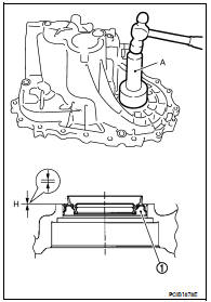
2. Install input shaft oil seal (1) to clutch housing using Tool (A).
Dimension “H” : 1.1 - 2.1 mm (0.043 - 0.083 in)
Tool number : ST35321000 ( — )
CAUTION: • Do not reuse input shaft oil seal.
• When installing, do not incline input shaft oil seal.
• Do not damage clutch housing.
3. Install differential side bearing outer race to clutch housing using Tool.
Tool number : ST30720000 (J-25405)
CAUTION: Replace differential side bearing and differential side bearing outer race as a set.
4. Install oil channel (1) on mainshaft side.
CAUTION: When installing oil channel, fit the rib (A) of oil channel into the processed area of the spot facing (B).
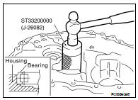
5. Install mainshaft front bearing to clutch housing using Tool.
Tool number : ST33200000 (J-26082)
CAUTION: Be careful with the orientation of mainshaft front bearing.
6. Install mainshaft bearing retainer (1) to clutch housing and tighten bolt to the specified torque.
2 : Mainshaft front bearing
3 : Oil channel
CAUTION: Install with punched surface facing up.
7. Install magnet to clutch housing.
8. Install final drive assembly into clutch housing.
9. Install input shaft assembly, mainshaft assembly, and reverse idler gear assembly into clutch housing.
CAUTION: • Wrap tape to the spline of input shaft so as not to damage the input shaft oil seal.
• Be careful with the orientation of reverse idler shaft.
10. Install striking rod assembly (1) into clutch housing.
CAUTION: • Check that return spring is securely seated in the groove on return pin.
11. Install 1st-2nd shift fork (1) and 1st-2nd fork rod (2) and then install retaining pin to 1st-2nd shift fork. CAUTION: • Do not reuse retaining pin.
• Be careful with the orientation of 1st-2nd shift fork and 1st-2nd fork rod.
• Assemble retaining pin from the direction shown until it becomes flush with the end surface of 1st-2nd shift fork.

12. Install 3rd-4th shift fork (1) to 3rd-4th coupling sleeve.
CAUTION: Be careful with the orientation of 3rd-4th shift fork.

13. Install 5th-6th shift fork (1) and 5th-6th fork rod (2) and then install retaining pin to 5th-6th shift fork.
CAUTION: • Do not reuse retaining pin.
• Be careful with the orientation of 5th-6th shift fork and 5th-6th fork rod.
• Assemble retaining pin from the direction shown until it becomes flush with the end surface of 5th-6th shift fork.
14. Install 3rd-4th fork rod (2) and then install retaining pin to 3rd-4th shift fork (1).
CAUTION: • Do not reuse retaining pin.
• Be careful with the orientation of 3rd-4th fork rod.
• Assemble retaining pin from the direction shown until it becomes flush with the end surface of 3rd-4th shift fork.

15. Install reverse shift fork (1) and reverse fork rod (2).
CAUTION: Be careful with the orientation of reverse shift fork and reverse fork rod.
16. Rotate striking lever of striking rod assembly as shown. Then rotate reverse fork rod to a position where bracket of reverse fork rod does not interfere with striking lever of striking rod assembly.
17. Install retaining pin to reverse shift fork (1).
2 : Reverse fork rod
CAUTION: • Do not reuse retaining pin.
• Assemble retaining pin from the direction shown until it becomes flush with the end surface of reverse shift fork.
18. Install selected differential side bearing adjusting shim(s) and differential side bearing outer race.
• For selection of adjusting shim(s), refer to TM-49, "Adjustment".
19. Install selected reverse idler gear adjusting shim onto reverse idler gear assembly.
• For selection of adjusting shim, refer to TM-49, "Adjustment".
20. Install selected input shaft rear bearing adjusting shim onto input shaft.
• For selection of adjusting shim, refer to TM-49, "Adjustment".
21. Install selected striking rod adjusting shim onto striking rod assembly.
• For selection of adjusting shim, refer to TM-49, "Adjustment".
22. Install shifter lever oil seal (1) and striking rod oil seal (2) to transaxle case using suitable tool.
Dimension “H” : 0 - 1.0 mm (0 - 0.039 in)
CAUTION: • Do not reuse shifter lever oil seal and striking rod oil seal.
• When installing, do not incline shifter lever oil seal and striking rod oil seal.
• Do not damage transaxle case.
23. Install differential side oil seal (1) to transaxle case using Tool (A) [SST: ST30720000 (J-25405)].
Dimension “H” : -0.5 - 0.5 mm (-0.020 - 0.020 in)
Tool number : ST30720000 (J-25405)
CAUTION: • Do not reuse differential side oil seal.
• When installing, do not incline differential side oil seal.
• Do not damage transaxle case.
24. Install shifter lever B (1) and shifter lever A (2) to transaxle case.
CAUTION: Be careful with the orientation of shifter lever B and shifter lever A.

25. Install retaining pin to shifter lever A.
CAUTION: • Do not reuse retaining pin.
• Assemble retaining pin from the direction shown until it becomes flush with the end surface of shifter lever A.
26. Install transaxle case according to the following: a. Install selected mainshaft rear bearing adjusting shim into transaxle case.
• For selection of adjusting shim, refer to TM-49, "Adjustment".
b. Install oil gutter A (1) and oil gutter B (2) to transaxle case.
CAUTION: Insert the tab (A) of oil gutter A and oil gutter B into transaxle case.
c. Temporarily install snap ring of mainshaft rear bearing into transaxle case.
CAUTION: Do not reuse snap ring.
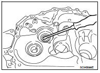
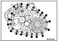
d. Apply recommended sealant to mating surface of clutch housing as shown.
• Use Genuine Silicone RTV or an equivalent. Refer to GI- 15, "Recommended Chemical Products and Sealants".
CAUTION: • Remove old sealant adhering to the mounting surfaces.
Also remove any moisture, oil, or foreign material adhering to both mounting surfaces.
• Apply sealant so as not to break the bead.
• The width of sealant bead is 1 - 2 mm (0.04 - 0.08 in).
• The height of sealant bead is 0.4 - 1 mm (0.016 - 0.04 in).
• The overlap length of both ends of sealant bead is 3 - 5 mm (0.12 - 0.20 in).
e. With shifter lever A (1) held in the position shown, temporarily assemble transaxle case to clutch housing.
CAUTION: Do not damage striking rod oil seal.
NOTE: Make sure to hold shifter lever A in the position shown. Otherwise transaxle case cannot be installed to clutch housing.
f. While rotating shifter lever A (1) in the direction shown, assemble transaxle case to clutch housing.
2 : Shifter lever B
g. Accessing from the bore plug hole, expand snap ring at mainshaft rear bearing so that the ring catches the periphery of mainshaft rear bearing.
h. Temporarily tighten transaxle case bolts.
i. Shift the shifter lever A (1) to 2nd gear position.
NOTE: • The 2nd gear position is attained when shifter lever A is in the position shown.
• When transaxle is shifted to the 2nd gear position, mainshaft assembly is lifted.
j. Seat snap ring in the groove on mainshaft rear bearing. If snap ring is not seated in the groove on mainshaft rear bearing, remove transaxle case and repeat the procedure from step d.
k. Tighten transaxle case bolts to the specified torque.
l. Shift the shifter lever A (1) to neutral position.
NOTE: The neutral position is attained when shifter lever A is in the position shown.
27. Install bore plug to transaxle case using Tool.
Tool number : ST33061000 (J-8107-2)
CAUTION: Do not reuse bore plug.
28. Install selector lever to transaxle case and then install retaining pin to selector lever.
CAUTION: • Do not reuse retaining pin.
• Assemble retaining pin from the direction shown until it becomes flush with the end surface of selector lever.
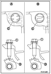
29. Install guide bolt (1) according to the following: a. Shift the shifter lever A and selector lever to neutral position (A).
b. Visually confirm from the guide bolt mounting hole (C) that shift lever A is securely set to neutral position (A). If it is not in the neutral position (B), repeat the procedure from step a.
CAUTION: The guide groove (D) of striking rod assembly will be damaged when assembling guide bolt (1) if the lever is not in the neutral position (B).
c. Check continuity between terminals of park/neutral position (PNP) switch to confirm it in the neutral position. If it is not in the neutral position, remove park/neutral position (PNP) switch and repeat the procedure from step a. Refer to TM-20, "Inspection".
d. Install guide bolt to transaxle case and then tighten guide bolt to the specified torque.
CAUTION: Do not reuse guide bolt.
30. Apply recommended sealant to threads of park/neutral position (PNP) switch (1). Then install it to transaxle case and tighten to the specified torque.
• Use Genuine Silicone RTV or an equivalent. Refer to GI- 15, "Recommended Chemical Products and Sealants".
CAUTION: Remove old sealant and oil adhering to threads. 31. Install plunger to transaxle case.
32. Apply recommended sealant to threads of back-up lamp switch (2). Then install it to transaxle case and tighten to the specified torque.
• Use Genuine Silicone RTV or an equivalent. Refer to GI- 15, "Recommended Chemical Products and Sealants".
CAUTION: Remove old sealant and oil adhering to threads.
33. Install air breather tube (3) to transaxle case.
CAUTION: • Do not reuse air breather tube.
• Assemble air breather tube until its collar element contacts with transaxle case.
34. Install gasket onto plug and then install them into transaxle case. Tighten plug to the specified torque.
CAUTION: Do not reuse gasket.
35. Install gasket onto drain plug and then install them into clutch housing. Tighten drain plug to the specified torque.
CAUTION: Do not reuse gasket. 36. Install O-ring onto plug (with ABS models) or speedometer pinion gear (without ABS models) and then install it into clutch housing. Tighten bolt to the specified torque.
CAUTION: • Do not reuse O-ring.
• After oil is filled, tighten bolt to specified torque.
Adjustment
DIFFERENTIAL SIDE BEARING PRELOAD
• When adjusting differential side bearing preload, select adjusting shim for differential side bearing. To select adjusting shim, measure clearance “L” between transaxle case and differential side bearing outer race.
CAUTION: Up to 2 adjusting shims can be selected. • Calculate dimension “L” (thickness of adjusting shim) using the following procedure to satisfy specification of preload for differential side bearing.
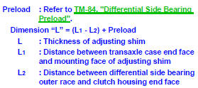
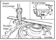
1. Using a depth micrometer and straightedge, measure dimension “L1” between transaxle case end face and mounting face of adjusting shim.
2. Install differential side bearing outer race onto differential side bearing on final gear side. Holding lightly differential side bearing outer race horizontally by hand, rotate final gear five times or more (for smooth movement of bearing roller).
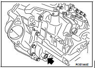
3. Using a depth micrometer and straightedge as shown, measure dimension “L2” between differential side bearing outer race and clutch housing end face.
CAUTION: “L2”: Measure at 4 point by approximately 90 degrees and use the average value.
4. Install selected differential side bearing adjusting shim and then install differential side bearing outer race using Tool.
Tool number : ST30720000 (J-25405)
CAUTION: Replace differential side bearing and differential side bearing outer race as a set.
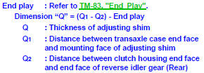
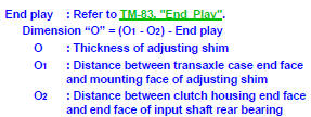
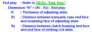
REVERSE IDLER GEAR END PLAY
• When adjusting reverse idler gear end play, select adjusting shim for reverse idler gear. To select adjusting shim (1), measure clearance between transaxle case (2) and reverse idler gear (Rear) (3).
CAUTION: Only 1 adjusting shim can be selected. • Calculate dimension “Q” (thickness of adjusting shim) using the following procedure to satisfy specification of end play for reverse idler gear.
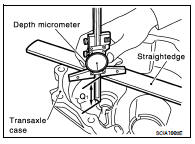
1. Using a depth micrometer and straightedge, measure dimension “Q1” between transaxle case end face and mounting face of adjusting shim.
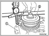
2. Using a depth micrometer and straightedge as shown, measure dimension “Q2” between clutch housing (1) end face and end face of reverse idler gear (Rear) (2).
CAUTION: “Q2”: Measure at 4 point by approximately 90 degrees and use the average value. 3. Install selected reverse idler gear adjusting shim onto reverse idler gear (Rear).
INPUT SHAFT END PLAY
• When adjusting input shaft end play, select adjusting shim for input shaft rear bearing. To select adjusting shim, measure clearance between transaxle case and input shaft rear bearing.
CAUTION: Only 1 adjusting shim can be selected.
• Calculate dimension “O” (thickness of adjusting shim) using the following procedure to satisfy specification of end play for input shaft rear bearing.
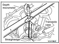
1. Using a depth micrometer and straightedge, measure dimension “O1” between transaxle case end face and mounting face of adjusting shim.
CAUTION: “O1”: Measure at 4 point by approximately 90 degrees and use the average value.
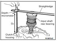
2. Using a depth micrometer and straightedge as shown, measure dimension “O2” between clutch housing end face and end face of input shaft rear bearing.
CAUTION: “O2”: Measure at 4 point by approximately 90 degrees and use the average value. 3. Install selected input shaft rear bearing adjusting shim onto input shaft.
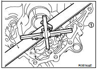
STRIKING ROD END PLAY
• When adjusting striking rod end play, select adjusting shim (1) for striking rod (2). To select adjusting shim, measure clearance between transaxle case (3) and striking rod shim (4).
CAUTION: Only 1 adjusting shim can be selected.
• Calculate dimension “R” (thickness of adjusting shim) using the following procedure to satisfy specification of end play for striking rod.
1. Using a depth micrometer (A) and straightedge (B), measure dimension “R1” between transaxle case (1) end face and mounting face of adjusting shim.
CAUTION: “R1”: Measure at 4 point by approximately 90 degrees and use the average value.
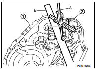
2. Using a depth micrometer (A) and straightedge (B) as shown, measure dimension “R2” between clutch housing (1) end face and end face of striking rod shim (2).
CAUTION: • “R2”: Measure at 4 point by approximately 90 degrees and use the average value.
• When measuring, be careful for the inclination of striking rod assembly and striking rod shim.
3. Install selected striking rod adjusting shim onto striking rod assembly.
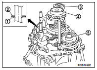
MAINSHAFT END PLAY
• When adjusting mainshaft end play, select adjusting shim (1) for mainshaft rear bearing (2). To select adjusting shim, measure clearance “M” between transaxle case (3) and dummy adjusting shim (4) on mainshaft rear bearing.
5 : Snap ring
6 : Mainshaft
CAUTION: Only 1 adjusting shim can be selected.
• Calculate dimension “P” (thickness of adjusting shim) using the following procedure to satisfy specification of end play for mainshaft rear bearing.

*: Refer to the latest parts information to use a dummy adjusting shim of which part number is the thinnest in thickness.
1. Install transaxle case according to the following: a. Temporarily install snap ring of mainshaft rear bearing into transaxle case.
CAUTION: Do not reuse snap ring.
b. Install dummy adjusting shim (1) to mainshaft assembly.
c. With shifter lever A (1) held in the position shown, temporarily assemble transaxle case to clutch housing.
CAUTION: Do not damage striking rod oil seal. NOTE: Make sure to hold shifter lever A in the position shown. Otherwise transaxle case cannot be installed to clutch housing.
d. While rotating shifter lever A (1) in the direction of the arrow shown, assemble transaxle case to clutch housing.
2 : Shifter lever B
e. Accessing from the bore plug hole, expand snap ring at mainshaft rear bearing so that the ring catches the periphery of mainshaft rear bearing.
f. Temporarily tighten transaxle case bolts.
2. Shift the shifter lever A to 2nd gear position.
NOTE: • The 2nd gear position is attained when shifter lever A (1) is in the position shown.
• When transaxle is shifted to the 2nd gear position, mainshaft assembly (1) is lifted.
3. Seat snap ring in the groove on mainshaft rear bearing. If snap ring is not seated in the groove on mainshaft rear bearing, remove transaxle case and repeat the procedure 1 from step c.
4. Shift the shifter lever A to 1st gear position, and then shift it to 2nd gear position. Repeat 3 times.
NOTE: • The mainshaft rear bearing position will be stabilized by shifting between 1st gear position and 2nd gear position alternately.
• The 1st gear position is attained when shifter lever A (1) is in the position shown.
• When transaxle is shifted to the 1st gear position, mainshaft assembly (1) is declined.
5. Set the dial indicator (A) to dummy adjusting shim (1) through the bore plug mounting hole.
2 : Mainshaft rear bearing
3 : Snap ring
M : Movement between 1st and 2nd gear
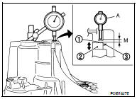
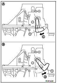
a. Shift the shifter lever A (1) to 2nd gear position (A), and then rotate it in the direction of the arrow (C) until it stops. Using this position as the reference point, measure the amount of movement when shifting shifter lever A to 1st gear position (B) and rotating it in the direction of the arrow (D) until it stops. This measurement is the "M" dimension.
b. When measurement "M" is 0 - 0.06 mm (0 - 0.0024 in), adjustment terminates, and the dummy adjusting shim becomes regular adjusting shim. Select adjusting shim from the computed expressions when measurement "M" is over 0.06 mm (0.0024 in).
 Disassembly and assembly
 Input shaft and gear