Nissan Altima (L32) 2007-2012 Service Manual: B2109 steering lock relay
Description
The steering lock relay ON signal is transmitted to IPDM E/R by BCM via CAN communication.
IPDM E/R turns the steering lock relay ON and transmits the release of the steering to BCM.
DTC Logic
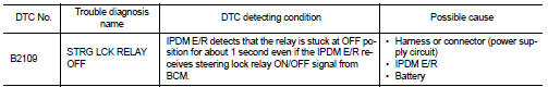
DTC DETECTION LOGIC
NOTE: • If DTC B2109 is displayed with DTC U1000, first perform the trouble diagnosis for DTC U1000. Refer to SEC-36, "DTC Logic".
• If DTC B2109 is displayed with DTC U1010, first perform the trouble diagnosis for DTC U1010. Refer to SEC-37, "DTC Logic".
DTC CONFIRMATION PROCEDURE
1.PERFORM DTC CONFIRMATION PROCEDURE
1. Press the push-button ignition switch under the following conditions and wait for at least 1 second.
- CVT selector lever is in the P or N position
- Do not depress the brake pedal
2. Check “Self diagnostic result” with CONSULT-III.
Is DTC detected? YES >> Refer to SEC-43, "Diagnosis Procedure".
NO >> Inspection End.
Diagnosis Procedure
1.CHECK POWER SUPPLY CIRCUIT
Check IPDM E/R power supply circuit. Refer to PCS-23, "Diagnosis Procedure".
Is the inspection result normal? YES >> GO TO 2
NO >> Repair the malfunctioning parts
2.CHECK FUSE
1. Turn ignition switch OFF.
2. Check 10A fuse (No. 40, located in IPDM E/R).
Is the inspection result normal? YES >> Replace IPDM E/R. Refer to PCS-48, "Removal and Installation".
NO >> Check the following.
• Harness for open or short between IPDM E/R and battery
• Fuse
 B2108 steering lock relay
 B210a steering lock condition switch