Nissan Altima (L32) 2007-2012 Service Manual: B2560 starter control relay
Description
Starter control relay, integrated in IPDM E/R, permits the starter relay
operation when in N or P position and
the steering is locked or unlocked. It is installed in parallel with the starter
relay.
DTC Logic
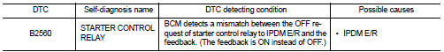
DTC DETECTION LOGIC
NOTE:
• If DTC B2560 is displayed with DTC U1000, first perform the trouble diagnosis
for DTC U1000. Refer to
SEC-36, "DTC Logic".
• If DTC B2560 is displayed with DTC U1010, first perform the trouble diagnosis
for DTC U1010. Refer to
SEC-37, "DTC Logic".
DTC CONFIRMATION PROCEDURE
1.PERFORM DTC CONFIRMATION PROCEDURE
1. Turn ignition switch ON under the following conditions and wait for at
least 2 seconds.
- CVT selector lever is in the P position
- Depress the brake pedal
2. Check “Self diagnostic result” with CONSULT-III.
Is DTC detected?
YES >> Refer to SEC-75, "Diagnosis Procedure".
NO >> Inspection End.
Diagnosis Procedure
1.CHECK DTC WITH IPDM E/R
Check “Self diagnostic result” with CONSULT-III. Refer to PCS-45, "DTC
Index".
Description
BCM receives the 2 vehicle speed signals via CAN communication. 1 signal is
transmitted by the “unified
meter” Another signal is transmitted by “ABS actuator and electric unit ( ...
Description
BCM confirms the shift position with the following 2 signals.
• CVT selector lever
• P position signal from IPDM E/R (CAN)
DTC Logic
DTC DETECTION LOGIC
NOTE:
• If DTC B260 ...
 B2557 vehicle speed
 B2601 shift position