Nissan Altima (L32) 2007-2012 Service Manual: Camshaft valve clearance
Camshaft valve clearance
• Perform this inspection as follows after removal, installation, or replacement of the camshaft or any valverelated parts, or if there are any unusual engine conditions due to changes in valve clearance over time (starting, idling, and/or noise).
1. Warm up the engine, then stop it.
2. Remove the fender protector side cover RH using power tool. Refer to EXT-19, "Removal and Installation" (Coupe models) or EXT-40, "Removal and Installation" (Sedan models).
3. Remove the rocker cover using power tool.
Refer to EM-39, "Removal and Installation".
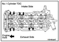
4. Turn crankshaft pulley in normal direction (clockwise when viewed from front) to align TDC identification mark (without paint mark) with timing indicator.
5. At this time, check that the both intake and exhaust cam lobes of No. 1 cylinder face outside.
• If they do not face outside, turn crankshaft pulley once more.
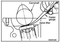
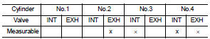
6. Measure valve clearances with a feeler gauge at locations marked (X) in the table below.
• No.1 cylinder compression TDC.
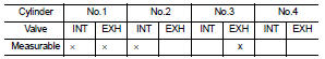
• Use a feeler gauge to measure the clearance between valve and camshaft.
*Approximately 80°C (176°F)
CAUTION: If inspection was carried out with cold engine, check that values with fully warmed up engine are still within specifications.
7. Turn crankshaft one complete revolution (360°) and align mark on crankshaft pulley with pointer.
8. Measure valve clearances with a feeler gauge at locations marked (X) in the table below.
• No.4 cylinder compression TDC.
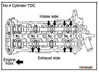
• If out of specifications, make necessary adjustment.
ADJUSTMENT
• Perform adjustment depending on selected head thickness of valve lifter.
• The specified valve lifter thickness is the dimension at normal temperatures. Ignore dimensional differences caused by temperature. Use the specifications for hot engine condition to adjust.
1. Remove camshaft. Refer to EM-41, "Removal and Installation".
2. Remove the valve lifters at the locations that are outside the standard.
3. Measure the center thickness of the removed valve lifters with a micrometer.
4. Use the equation below to calculate valve lifter thickness for replacement.
• Valve lifter thickness calculation.
t = t1 + (C1 - C2)
t = Thickness of replacement valve lifter.
t1 = Thickness of removed valve lifter.
C1 = Measured valve clearance.
C2 = Standard valve clearance.
• Thickness of a new valve lifter can be identified by stamp marks on the reverse side (inside the cylinder).
Stamp mark 696 indicates a thickness of 6.96 mm (0.2740 in) Available thickness of valve lifter: 26 sizes with a range of 7.88 to 8.38 mm (0.3102 to 0.3299 in), in steps of 0.02 mm (0.0008 in), when assembled at the factory.
5. Install the selected valve lifter.
6. Install camshaft.
7. Manually turn crankshaft pulley a few turns.
8. Check that valve clearances for cold engine are within specifications, by referring to the specified values.
9. After completing the repair, check valve clearances again with the specifications for warmed engine. Use a feeler gauge to measure the clearance between the valve and camshaft. Make sure the values are within specifications.
* Approximately 80C° (176°F)
 Air cleaner filter
 Compression pressure