Nissan Altima 2007-2012 Service Manual: Charging system
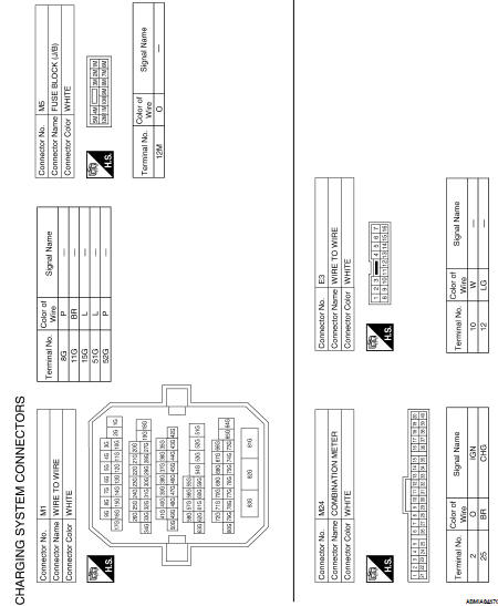
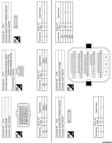
Wiring Diagram - Coupe
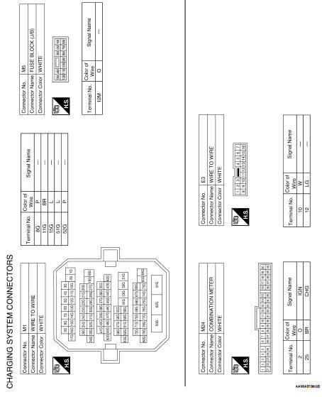
Wiring Diagram - Sedan
S Terminal circuit
Description The output voltage of the generator is controlled by the IC regulator at terminal “3” (S) detecting the input voltage. Terminal “3” circuit detects the battery voltage to adj ...Symptom diagnosis
CHARGING SYSTEM Symptom Table ...Other materials:
Fuel level sensor unit, fuel filter
and fuel pump assembly
Exploded View
1. Lock ring
2. Fuel level sensor unit, fuel filter and
fuel pump assembly
3. O-ring
4. Fuel Tank
Removal and Installation
REMOVAL
WARNING:
Read “General Precautions” before working on the fuel system.
Refer to GI-28, "General Precautions".
1. Unscrew the ...
P0122, P0123 TP Sensor
Description
Electric throttle control actuator consists of throttle control motor,
throttle position sensor, etc. The throttle position sensor responds to
the throttle valve movement.
The throttle position sensor has two sensors. These sensors are a
kind of potentiometers which transform the ...
P0500 VSS
Description
The vehicle speed signal is sent to the combination meter from the “ABS
actuator and electric unit (control
unit)” by CAN communication line. The combination meter then sends a signal to
the ECM by CAN communication
line.
DTC Logic
DTC DETECTION LOGIC
NOTE:
• If DTC P050 ...