Nissan Altima (L32) 2007-2012 Service Manual: ECU diagnosis
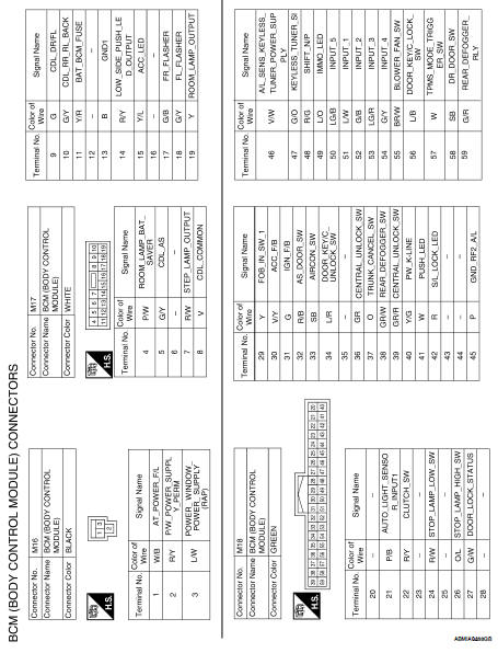
BCM (BODY CONTROL MODULE)
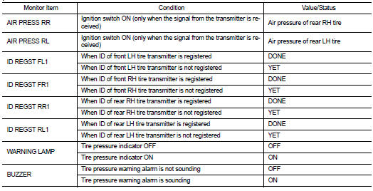
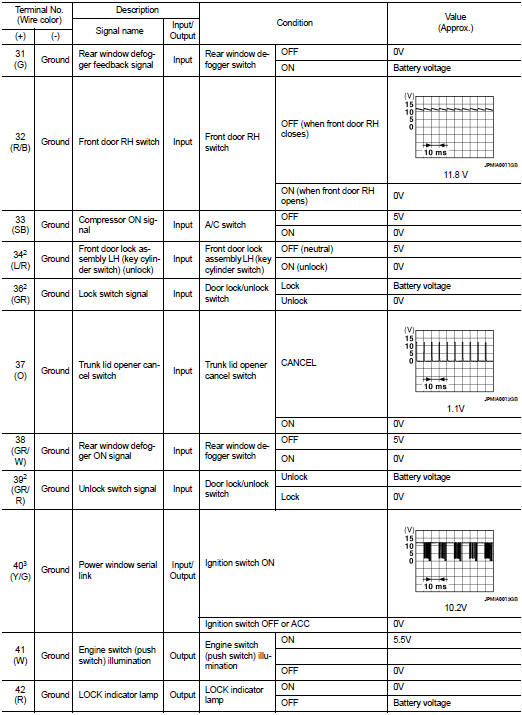
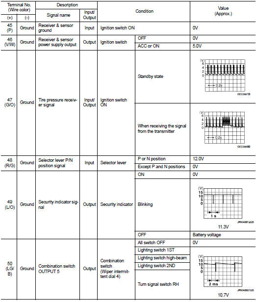
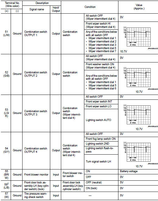
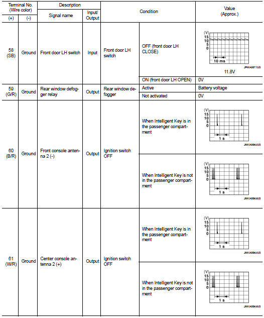
Reference Value
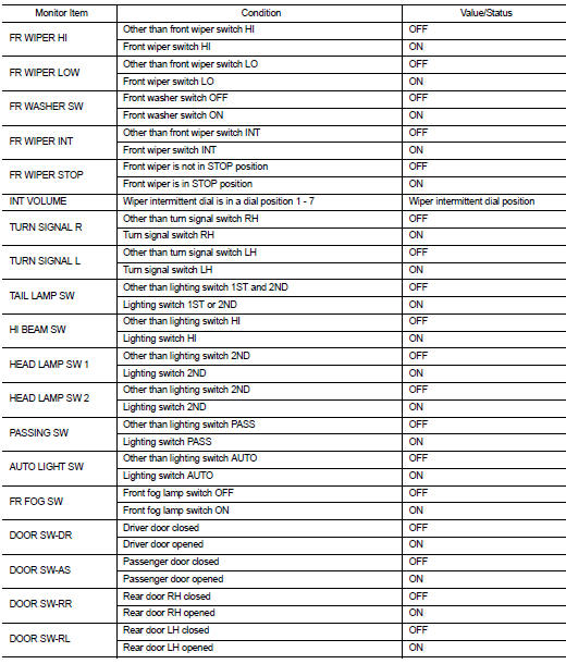
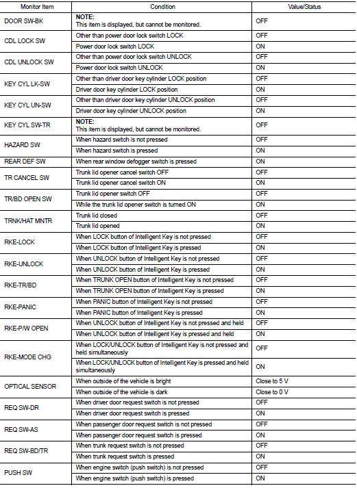
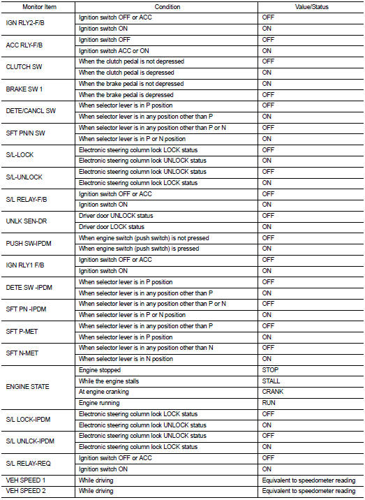
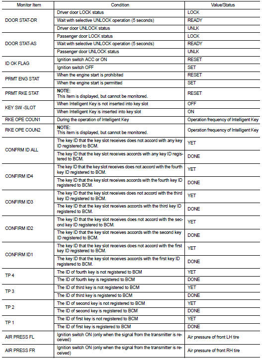
VALUES ON THE DIAGNOSIS TOOL
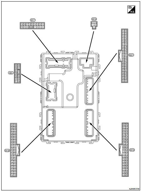
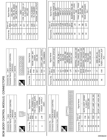
Terminal Layout
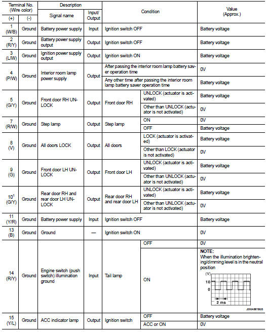
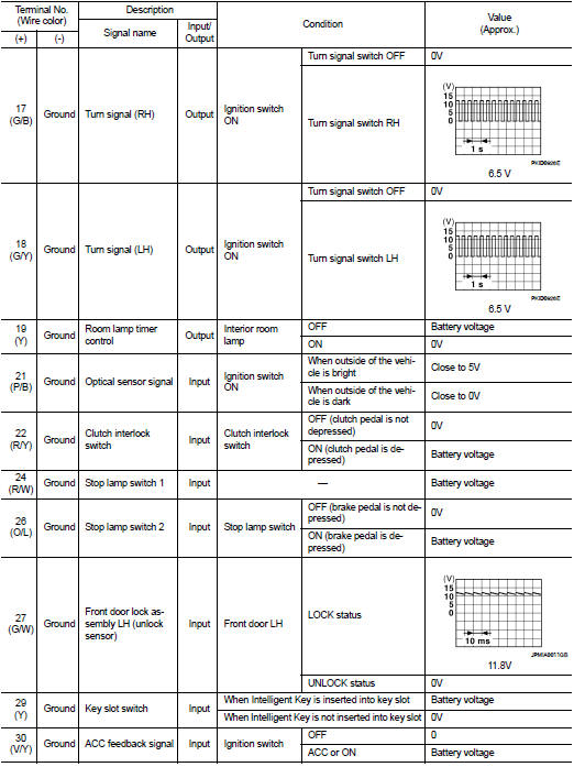
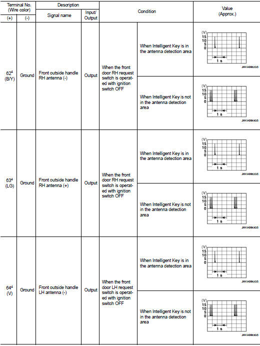
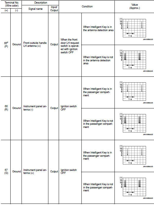
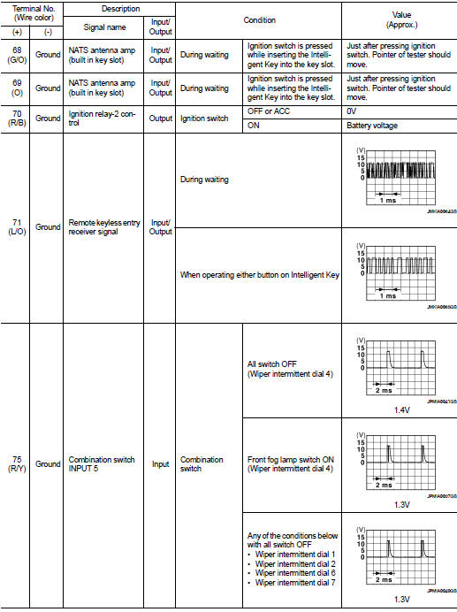
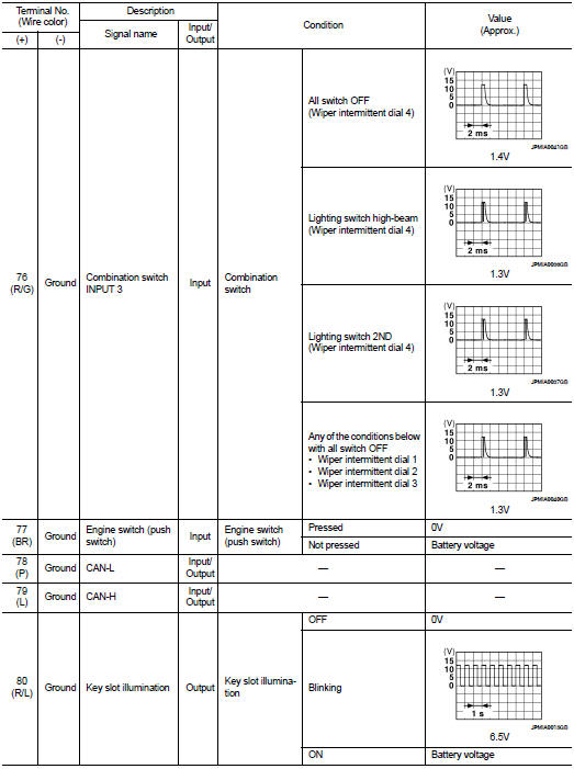
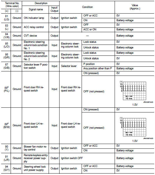
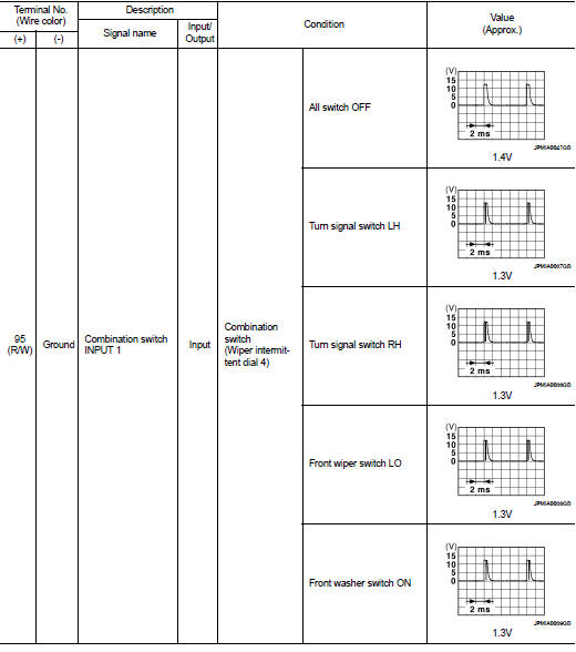
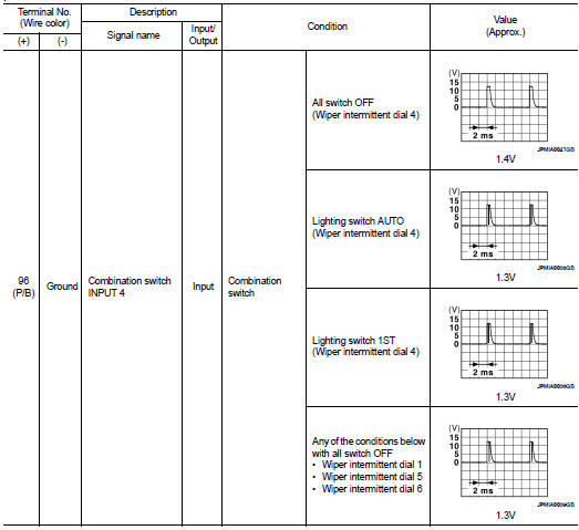
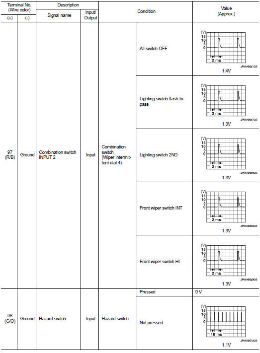
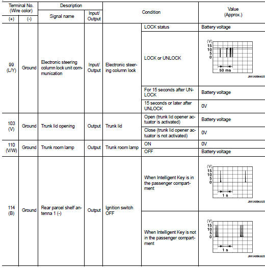
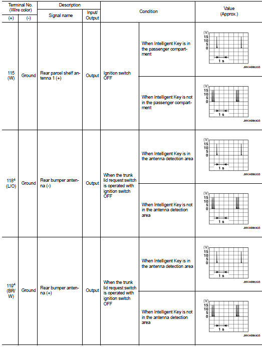
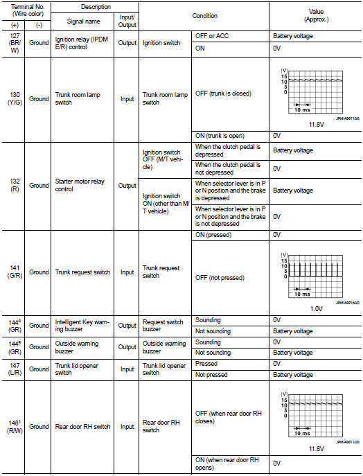
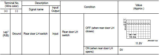
Physical Values
1: Sedan only
2: With LH front window anti-pinch
3: With LH and RH front window anti-pinch
4: With Intelligent Key
5: Without Intelligent Key
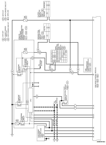
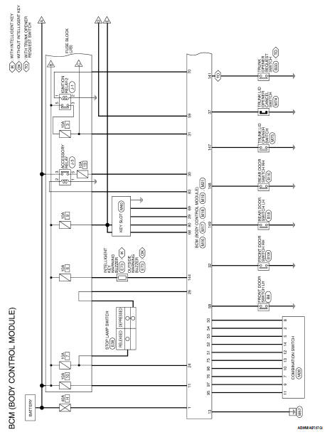
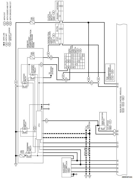
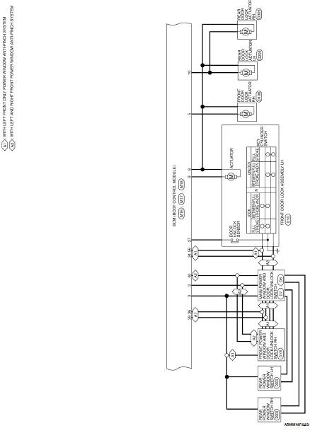
Wiring Diagram-Coupe
Wiring Diagram-Sedan
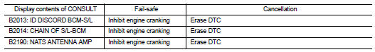
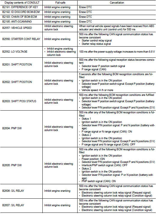
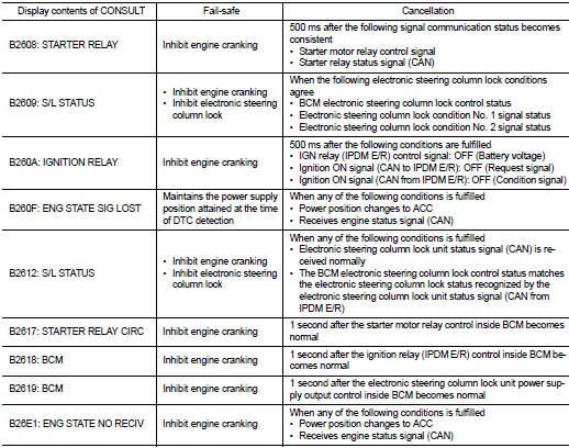
Fail Safe
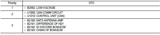
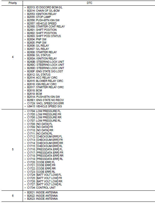
DTC Inspection Priority Chart
If some DTCs are displayed at the same time, perform inspections one by one
based on the following priority
chart.
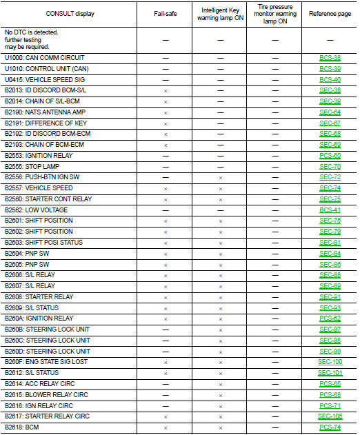
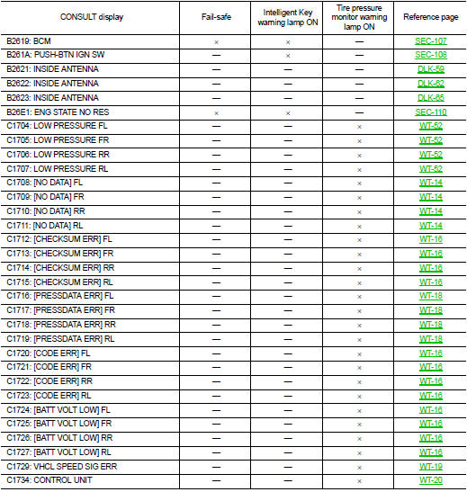
DTC Index
NOTE:
Details of time display
• CRNT: Displays when there is a malfunction now or after returning to the
normal condition until turning ignition
switch OFF → ON again.
• 1 - 39: Displayed if any previous malfunction is present when current
condition is normal. It increases like 1
→ 2 → 3...38 → 39 after returning to the normal condition whenever ignition
switch OFF → ON. The counter
remains at 39 even if the number of cycles exceeds it. It is counted from 1
again when turning ignition switch
OFF → ON after returning to the normal condition if the malfunction is detected
again.
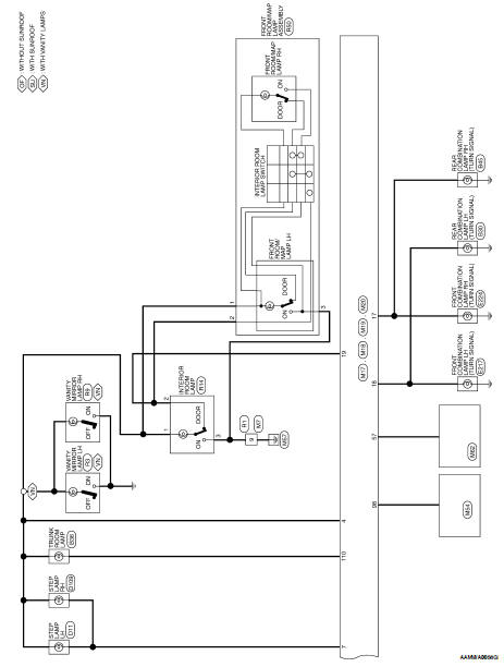
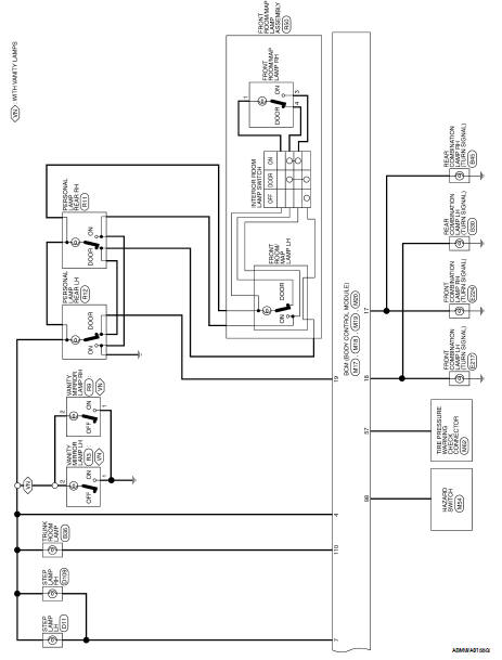
INTERIOR ROOM LAMP CONTROL SYSTEM
System Diagram
System Description
OUTLINE
• Interior room lamps* are controlled by interior room lamp timer control
function of BCM.
*:Front room/map l ...
INTERIOR LIGHTING SYSTEM SYMPTOMS
Symptom Table
CAUTION:
Perform the self-diagnosis with CONSULT-III before the symptom diagnosis.
Perform the trouble diagnosis
if any DTC is detected.
...
 Function diagnosis
 Symptom diagnosis