Nissan Altima (L32) 2007-2012 Service Manual: Engine coolant temperature gauge
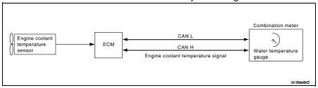
System Diagram
System Description
The engine coolant temperature gauge indicates the engine coolant
temperature.
The ECM provides an engine coolant temperature signal to the combination meter
via CAN communication
lines.
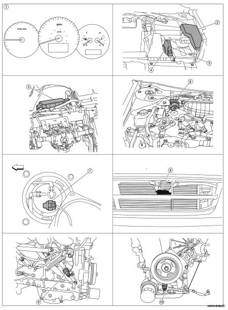
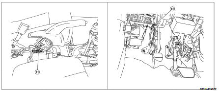
Component Parts Location
1. Combination meter M24
2. IPDM E/R E17, E18, E201, F10
3. ECM E10
4. TCM F16
5. BCM M17, M18, M19, M21 (view with
instrument panel removed)
6. ABS actuator and electric unit (control
unit) E26
7. Fuel level sensor unit and fuel pump
(fuel level sensor) B42 (view with rear
seat and inspection hole cover removed)
8. Ambient sensor E211 (view of front
bumper fascia)
9. Oil pressure switch F41 (QR25DE)
(view with engine removed)
10. Oil pressure switch F41 (VQ35DE)
(view with engine removed)
11. Parking brake switch M73
(Sedan with M/T and Coupe)
(view with center console removed)
12. Parking brake switch E35
(Sedan with CVT)
(view with instrument lower cover LH
removed)
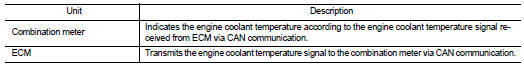
Component Description
System Diagram
System Description
The tachometer indicates engine speed in revolutions per minute (rpm).
The ECM provides an engine speed signal to the combination meter via CAN
commu ...
System Diagram
System Description
The fuel gauge indicates the approximate fuel level in the fuel tank.
The fuel gauge is regulated by the unified meter control unit and a variable
resistor s ...
Other materials: Speedometer and odometer
This vehicle is equipped with a speedometer
and odometer. The speedometer is
located on the right side of the meter
cluster. The odometer is located within the
vehicle information display.
5 inch (13 cm) Type A (if so equipped)
Speedometer
The speedometer indicates vehicle speed.
7 inch (18 cm) Ty ...
Warning/Indicator lights (other)
For additional information on warnings
and indicators, see "Vehicle information
display-5 inch (13 cm) Type A" or
"Vehicle information display 7 inch (18 cm)
Type B".
Automatic brake hold
indicator light (white/green)
(if so equipped)
The automatic brake hold indicator light
(white) illuminates whe ...
Settings
The setting mode allows you to change the
information displayed in the vehicle information
display. It also allows you to change
vehicle functions:
VDC
Driver Assistance
Clock
Meter Settings
Vehicle Settings
Maintenance
Alarm
Tire Pressures
Unit
Language
Factory Reset
VDC
The VDC Settin ...
 Tachometer
 Fuel gauge