Nissan Altima (L32) 2007-2012 Service Manual: P0171 fuel injection system function
DTC Logic
DTC DETECTION LOGIC
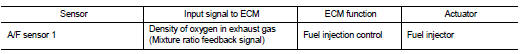
With the Air/Fuel Mixture Ratio Self-Learning Control, the actual mixture ratio can be brought closely to the theoretical mixture ratio based on the mixture ratio feedback signal from the A/F sensors 1. The ECM calculates the necessary compensation to correct the offset between the actual and the theoretical ratios.
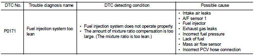
In case the amount of the compensation value is extremely large (The actual mixture ratio is too lean.), the ECM judges the condition as the fuel injection system malfunction and lights up the MIL (2 trip detection logic).
DTC CONFIRMATION PROCEDURE
1.PRECONDITIONING
If DTC Confirmation Procedure has been previously conducted, always turn ignition switch OFF and wait at least 10 seconds before conducting the next test.
>> GO TO 2.
2.PERFORM DTC CONFIRMATION PROCEDURE-I
1. Clear the mixture ratio self-learning value. Refer to EC-32, "MIXTURE RATIO SELF-LEARNING VALUE CLEAR : Special Repair Requirement".
2. Start engine.
Is it difficult to start engine? YES >> GO TO 3.
NO >> GO TO 4.
3.RESTART ENGINE
If it is difficult to start engine, the fuel injection system has a malfunction, too.
Crank engine while depressing accelerator pedal.
NOTE: When depressing accelerator pedal three-fourths (3/4) or more, the control system does not start the engine. Do not depress accelerator pedal.
Does engine start? YES >> Go to EC-255, "Diagnosis Procedure".
NO >> Check exhaust and intake air leak visually.
4.PERFORM DTC CONFIRMATION PROCEDURE-II
1. Start engine and let it idle for at least 5 minutes.
2. Check 1st trip DTC.
Is 1st trip DTC detected? YES >> Go to EC-255, "Diagnosis Procedure".
NO >> GO TO 5.
5.PERFORM DTC CONFIRMATION PROCEDURE-III
1. Turn ignition switch OFF and wait at least 10 seconds.
2. Start engine.
3. Maintain the following conditions for at least 10 consecutive minutes.
Hold the accelerator pedal as steady as possible.
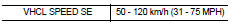
CAUTION: Always drive vehicle at a safe speed.
4. Check 1st trip DTC.
Is 1st trip DTC detected? YES >> Go to EC-255, "Diagnosis Procedure".
NO >> INSPECTION END
Diagnosis Procedure
1.CHECK EXHAUST GAS LEAK
1. Start engine and run it at idle.
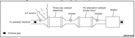
2. Listen for an exhaust gas leak before three way catalyst (manifold).
Is exhaust gas leak detected? YES >> Repair or replace.
NO >> GO TO 2.
2.CHECK FOR INTAKE AIR LEAK
1. Listen for an intake air leak after the mass air flow sensor.
2. Check PCV hose connection.
Intake air leak detected? YES >> Repair or replace.
NO >> GO TO 3.
3.CHECK A/F SENSOR 1 INPUT SIGNAL CIRCUIT
1. Turn ignition switch OFF.
2. Disconnect corresponding A/F sensor 1 harness connector.
3. Disconnect ECM harness connector.
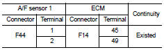
4. Check the continuity between A/F sensor 1 harness connector and ECM harness connector.
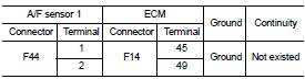
5. Check the continuity between A/F sensor 1 harness connector or ECM harness connector and ground.
6. Also check harness for short to power.
Is the inspection result normal? YES >> GO TO 4.
NO >> Repair open circuit or short to ground or short to power in harness or connectors.
4.CHECK FUEL PRESSURE
1. Check fuel pressure. Refer to EC-550, "Inspection".
Is the inspection result normal? YES >> GO TO 6.
NO >> GO TO 5.
5. DETECT MALFUNCTIONING PART
Check fuel hoses and fuel tubes for clogging.
Is the inspection result normal? YES >> Replace “fuel filter and fuel pump assembly”.
NO >> Repair or replace
6.CHECK MASS AIR FLOW SENSOR

1. Install all removed parts.
2. Check “MASS AIR FLOW” in “DATA MONITOR” mode with CONSULT-III.
3. For specification, refer to EC-555, "Mass Air Flow Sensor".

1. Install all removed parts.
2. Check mass air flow sensor signal in Service $01 with GST.
3. For specification, refer to EC-555, "Mass Air Flow Sensor".
Is the measurement value within the specification? YES >> GO TO 7.
NO >> Check connectors for rusted terminals or loose connections in the mass air flow sensor circuit or grounds. Refer to EC-168, "DTC Logic".
7.CHECK FUNCTION OF FUEL INJECTOR

1. Start engine.
2. Perform “POWER BALANCE” in “ACTIVE TEST” mode with CONSULT-III.
3. Make sure that each circuit produces a momentary engine speed drop.

1. Let engine idle.
2. Listen to each fuel injector operating sound.
Clicking noise should be heard.
Is the inspection result normal? YES >> GO TO 8.
NO >> Perform trouble diagnosis for FUEL INJECTOR, refer to EC-463, "Component Function Check".
8.CHECK FUEL INJECTOR
1. Turn ignition switch OFF.
2. Confirm that the engine is cooled down and there are no fire hazards near the vehicle.
3. Disconnect all fuel injector harness connectors.
4. Remove fuel tube assembly. Refer to EM-36, "Removal and Installation".
Keep fuel hose and all fuel injectors connected to fuel tube.
5. Disconnect all ignition coil harness connectors.
6. Prepare pans or saucers under each fuel injector.
7. Crank engine for about 3 seconds.
Fuel should be sprayed evenly for each fuel injector.
Is the inspection result normal? YES >> GO TO 9.
NO >> Replace fuel injectors from which fuel does not spray out. Always replace O-ring with new ones.
9.CHECK INTERMITTENT INCIDENT
Refer to GI-42, "Intermittent Incident".
>> INSPECTION END
 P0146 HO2S3
 P0172 fuel injection system function