Nissan Altima 2007-2012 Service Manual: Parking brake release warning chime
System Diagram
System Description
DESCRIPTION
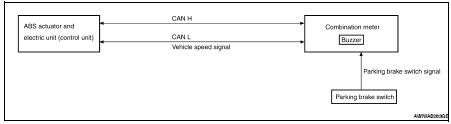
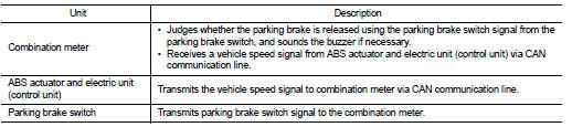
• The combination meter receives the vehicle speed signal from the ABS actuator and electric unit (control unit) via CAN communication line.
• The combination meter judges whether the parking brake is released using the parking brake switch signal from the parking brake switch, and sounds the warning buzzer if necessary.
WARNING OPERATION CONDITIONS
If all of the following conditions are fulfilled
• Vehicle speed is approximately 7 km/h (4.3 MPH) or higher
• Parking brake switch ON
WARNING CANCEL CONDITIONS
Warning is canceled if any of the following conditions is fulfilled.
• Vehicle speed is approximately 3 km/h (1.9 MPH) or less
• Parking brake switch OFF
Component Parts Location
1. Combination meter M24
2. Combination switch (lighting switch) M28
3. Seat belt buckle switch LH B202
4. Door switch LH B8
5. BCM M16, M17, M18, M19 (view with instrument panel removed)
6. ABS actuator and electric unit (control unit) E26
7. Parking brake switch M73 (sedan with M/T or coupe) (view with center console removed)
8. Parking brake switch E35 (sedan with CVT) [view with instrument panel lower cover (LH) removed]
Component Description
Seat belt warning chime
System Diagram System Description DESCRIPTION With ignition switch turned ON and driver seat belt unfastened, seat belt warning chime will sound for approximately 6 seconds. • BCM receive ...Diagnosis system (meter)
Diagnosis Description SELF-DIAGNOSIS MODE • Odo/trip meter and information display segment operation can be checked in self-diagnosis mode. • Meters/gauges can be checked in self-diagnosis ...Other materials:
Hands free phone system (coupe)
System Diagram
System Description
Refer to the owner's manual for Bluetooth telephone system operating
instructions.
NOTE:
Cellular telephones must have their wireless connection set up (paired) before
using the Bluetooth telephone
system.
Bluetooth telephone system allows users who ...
Power steering oil pump
QR25DE : Exploded View
1. Rear bracket
2. Pump assembly
3. Front bracket
Removal and Installation
REMOVAL
1. Drain power steering fluid from reservoir tank.
2. Remove undercover using power tool.
3. Loosen drive belt. Refer to EM-16, "Removal and Installation".
4. Remove d ...
Main line between DLC and ABS circuit
Diagnosis Procedure
INSPECTION PROCEDURE
1.CHECK CONNECTOR
1. Turn the ignition switch OFF.
2. Disconnect the battery cable from the negative terminal.
3. Check the following terminals and connectors for damage, bend and loose
connection (connector side
and harness side).
- Harness co ...