Nissan Altima (L32) 2007-2012 Service Manual: Precaution
Precaution for Supplemental Restraint System (SRS) "AIR BAG" and "SEAT BELT PRE-TENSIONER" The Supplemental Restraint System such as “AIR BAG” and “SEAT BELT PRE-TENSIONER”, used along with a front seat belt, helps to reduce the risk or severity of injury to the driver and front passenger for certain types of collision. This system includes seat belt switch inputs and dual stage front air bag modules. The SRS system uses the seat belt switches to determine the front air bag deployment, and may only deploy one front air bag, depending on the severity of a collision and whether the front occupants are belted or unbelted.
Information necessary to service the system safely is included in the SR and SB section of this Service Manual.
WARNING: • To avoid rendering the SRS inoperative, which could increase the risk of personal injury or death in the event of a collision which would result in air bag inflation, all maintenance must be performed by an authorized NISSAN/INFINITI dealer.
• Improper maintenance, including incorrect removal and installation of the SRS, can lead to personal injury caused by unintentional activation of the system. For removal of Spiral Cable and Air Bag Module, see the SR section.
• Do not use electrical test equipment on any circuit related to the SRS unless instructed to in this Service Manual. SRS wiring harnesses can be identified by yellow and/or orange harnesses or harness connectors.
Precautions Necessary for Steering Wheel Rotation after Battery Disconnect
NOTE: • Before removing and installing any control units, first turn the push-button ignition switch to the LOCK position, then disconnect both battery cables.
• After finishing work, confirm that all control unit connectors are connected properly, then re-connect both battery cables.
• Always use CONSULT-III to perform self-diagnosis as a part of each function inspection after finishing work.
If a DTC is detected, perform trouble diagnosis according to self-diagnosis results.
This vehicle is equipped with a push-button ignition switch and a steering lock unit.
If the battery is disconnected or discharged, the steering wheel will lock and cannot be turned.
If turning the steering wheel is required with the battery disconnected or discharged, follow the procedure below before starting the repair operation.
OPERATION PROCEDURE
1. Connect both battery cables.
NOTE: Supply power using jumper cables if battery is discharged.
2. Carry the Intelligent Key or insert it to the key slot and turn the push-button ignition switch to ACC position.
(At this time, the steering lock will be released.) 3. Disconnect both battery cables. The steering lock will remain released with both battery cables disconnected and the steering wheel can be turned.
4. Perform the necessary repair operation.
5. When the repair work is completed, re-connect both battery cables. With the brake pedal released, turn the push-button ignition switch from ACC position to ON position, then to LOCK position. (The steering wheel will lock when the push-button ignition switch is turned to LOCK position.) 6. Perform self-diagnosis check of all control units using CONSULT-III.
Precaution for Procedure without Cowl Top Cove
When performing the procedure after removing cowl top cover, cover the lower end of windshield with urethane, etc.
Service Notice or Precautions
• Always use recommended fluid. Refer to MA-12, "Fluids and Lubricants".
• Never reuse drained fluid.
• Be careful not to splash fluid on painted areas.
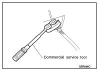
• When removing and installing clutch piping, use tool.
• Use new fluid to clean or wash all parts of master cylinder.
• Never use mineral oils such as gasoline or kerosene. It will ruin the rubber parts of the hydraulic system.
WARNING: After cleaning clutch disc, wipe it with a dust collector. Do not use compressed air.
 Symptom diagnosis
 Preparation