Nissan Altima (L32) 2007-2012 Service Manual: Relay control system
System Diagram
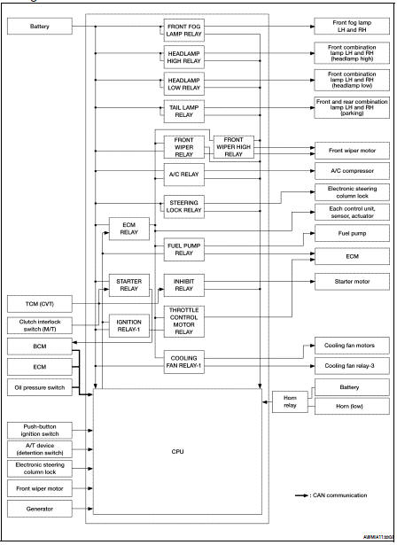
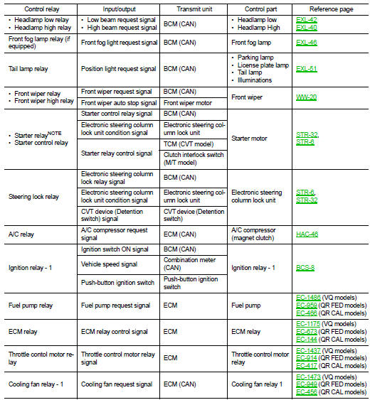
System Description
IPDM E/R activates the internal control circuit to perform the relay ON-OFF
control according to the input signals
from various sensors and the request signals received from control units via CAN
communication.
CAUTION:
IPDM E/R integrated relays cannot be removed.
System Diagram
System Description
COOLING FAN CONTROL
IPDM E/R controls cooling fans according to the status of the cooling fan
speed request signal received from
ECM via CAN communication. R ...
 Function diagnosis
 Power control system