Nissan Altima (L32) 2007-2012 Service Manual: Air mix door motor
Description
SYSTEM DESCRIPTION
Component Parts
Air mix door control system components are: • Front air control
• Air mix door motors (LCU)
• In-vehicle sensor
• Ambient sensor
• Sunload sensor
• Intake sensor
System Operation
The front air control receives data from each of the sensors. The front air control sends air mix door, mode door and intake door motor opening angle data to the air mix door motors LCU, mode door motor LCU and intake door motor LCU.
The air mix door motor, mode door motor and intake door motor read their respective signals according to the address signal. Opening angle indication signals received from the front air control and each of the motor position sensors are compared by the LCUs in each motor with the existing decision and opening angles. Subsequently, HOT/COLD or DEFROST/VENT or FRESH/RECIRCULATION operation is selected. The new selection data is returned to the front air control.
Air Mix Door Control Specification
COMPONENT DESCRIPTION
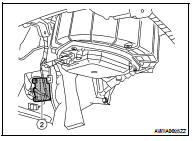
Air Mix Door Motor
The air mix door motors LH (1) RH (2) are attached to the heater & cooling unit assembly. They rotates so that the air mix door is opened or closed to a position set by the front air control. Motor rotation is then conveyed through a shaft and the air mix door position feedback is then sent to the front air control by PBR built-in air mix door motor.
Diagnosis Procedure
SYMPTOM: • Discharge air temperature does not change.
• Air mix door motor does not operate.
INSPECTION FLOW
1. CONFIRM SYMPTOM BY PERFORMING OPERATION CHECK - TEMPERATURE INCREASE
1. Turn the temperature control dial (LH) clockwise until 32°C (90°F) is displayed.
2. Check for hot air at discharge air outlets.
>> GO TO 2
2. CONFIRM SYMPTOM BY PERFORMING OPERATION CHECK - TEMPERATURE DECREASE
1. Turn the temperature control dial (LH) counterclockwise until 18°C (60°F) is displayed.
2. Check for cold air at discharge air outlets.
Can a symptom be duplicated? YES >> GO TO 4
NO >> GO TO 3
3. PERFORM COMPLETE OPERATIONAL CHECK
Perform a complete operational check and check for any symptoms. Refer to HAC-5, "Description and Conditions".
Is the inspection result normal? YES >> Refer to HAC-83, "Symptom Matrix Chart".
NO >> System OK.
4. CHECK FOR SERVICE BULLETINS
Check for any service bulletins.
>> GO TO 5
5. CHECK AIR MIX DOOR MOTOR OPERATION
Check and verify air mix door mechanism for smooth operation.
Is the inspection result normal? YES >> GO TO 6
NO >> Repair as necessary.
6. CHECK LAN SYSTEM CIRCUIT
Perform diagnostic procedure for the LAN system. Refer to HAC-28, "Diagnosis Procedure".
Is the inspection result normal? YES >> GO TO 7
NO >> Repair as necessary.
7. CHECK AMBIENT SENSOR CIRCUIT
Perform diagnostic procedure for the mode door motor. Refer to HAC-32, "Diagnosis Procedure".
Is the inspection result normal? YES >> GO TO 8
NO >> Repair as necessary.
8. CHECK IN-VEHICLE SENSOR CIRCUIT
Perform diagnostic procedure for the in-vehicle sensor circuit. Refer to HAC-53, "Diagnosis Procedure".
Is the inspection result normal? YES >> GO TO 9
NO >> Repair as necessary.
9. CHECK SUNLOAD SENSOR CIRCUIT
Perform diagnostic procedure for the sunload sensor circuit. Refer to HAC-56, "Diagnosis Procedure".
Is the inspection result normal? YES >> GO TO 10
NO >> Repair as necessary.
10. CHECK INTAKE SENSOR CIRCUIT
Perform diagnostic procedure for the intake sensor circuit. Refer to HAC-59, "Diagnosis Procedure".
Is the inspection result normal? YES >> GO TO 11
NO >> Repair as necessary.
11. CHECK AIR MIX DOOR MOTOR PBR CIRCUIT
Perform diagnostic procedure for the intake sensor circuit. Refer to HAC-35, "Diagnosis Procedure".
Is the inspection result normal? YES >> GO TO 12
NO >> Repair as necessary.
12. RECHECK FOR SYMPTOMS
Perform a complete operational check and check for any symptoms. Refer to HAC-5, "Description and Conditions".
Does another symptom exist? YES >> Repair as necessary.
NO >> Replace front air control. Refer to VTL-8, "Removal and Installation".
DIAGNOSIS PROCEDURE FOR AIR MIX DOOR MOTOR
SYMPTOM: Discharge air temperature does not change.
Perform diagnosis procedure. Refer to HAC-28, "Diagnosis Procedure".
 Mode door motor
 Intake door motor