Nissan Altima (L32) 2007-2012 Service Manual: Audio antenna (sedan)
Location of Antenna
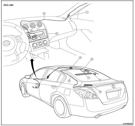
1. In-line connectors M87, M501
2. Audio unit harness
3. Audio unit
4. Satellite antenna
5. Audio antenna feeder
6. Satellite radio antenna feeder
7. Window Antenna
8. Antenna amp.
9. Satellite radio tuner
Window Antenna Repair
ELEMENT CHECK
1. Attach probe circuit tester (ohm setting) to antenna terminal on each side.
• When measuring continuity, wrap tin foil around the top of probe. Then, press the foil against the wire with your finger.
2. If an element is broken, no continuity will exist.
3. To locate a break, move probe along element. Tester indication will change abruptly when probe passes the broken point.
REPAIR EQUIPMENT
• Conductive silver composition (DuPont No. 4817 or equivalent)
• Ruler 30 cm (11.8 in) long
• Drawing pen
• Heat gun
• Alcohol
• Cloth
REPAIRING PROCEDURE
1. Wipe broken heat wire and its surrounding area clean with a cloth dampened in alcohol.
2. Apply a small amount of conductive silver composition to tip of drawing pen.
Shake silver composition container before use.
3. Place ruler on glass along broken line. Deposit conductive silver composition on break with drawing pen. Slightly overlap existing heat wire on both sides [preferably 5 mm (0.20 in)] of the break.
4. After repair has been completed, check repaired wire for continuity.
This check should be conducted 10 minutes after silver composition is deposited.
Do not touch repaired area while test is being conducted.
5. Apply a constant stream of hot air directly to the repaired area for approximately 20 minutes with a heat gun. A minimum distance of 3 cm (1.2 in) should be kept between repaired area and hot air outlet.
If a heat gun is not available, let the repaired area dry for 24 hours.
 Audio antenna (coupe)
 Antenna AMP