Nissan Altima (L32) 2007-2012 Service Manual: Automatic speed control device (ASCD)
System Diagram
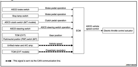
System Description
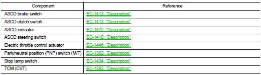
INPUT/OUTPUT SIGNAL CHART
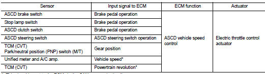
*: This signal is sent to the ECM via the CAN communication line
BASIC ASCD SYSTEM
Refer to Owner's Manual for ASCD operating instructions.
Automatic Speed Control Device (ASCD) allows a driver to keep vehicle at predetermined constant speed without depressing accelerator pedal. Driver can set vehicle speed in advance between approximately 40 km/ h (25 MPH) and 144 km/h (89 MPH).
ECM controls throttle angle of electric throttle control actuator to regulate engine speed.
The ASCD operation status is indicated by two indicators (CRUISE and SET on the information display) on the combination meter. If any malfunction occurs in the ASCD system, SET indicator blinks and ASCD control is deactivated.
NOTE: Always drive vehicle in a safe manner according to traffic conditions and obey all traffic laws.
SET OPERATION
Press MAIN switch. (CRUISE is indicated on the information display.) When vehicle speed reaches a desired speed between approximately 40 km/h (25 MPH) and 144 km/h (89 MPH), press SET/COAST switch. (Then SET is indicated on the information display in combination meter.)
ACCELERATE OPERATION
If the RESUME/ACCELERATE switch is pressed during cruise control driving, increase the vehicle speed until the switch is released or vehicle speed reaches maximum speed controlled by the system.
And then ASCD will maintain the new set speed.
CANCEL OPERATION
When any of following conditions exist, cruise operation will be canceled.
• CANCEL switch is pressed
• More than 2 switches on ASCD steering switch are pressed at the same time (Set speed will be cleared) • Brake pedal is depressed
• Selector lever position is changed to N, P or R (CVT models) • Vehicle speed decreased to 13 km/h (8 MPH) lower than the set speed
• TCS system is operated
• CVT control system has a malfunction. Refer to EC-1423, "Description".
When the ECM detects any of the following conditions, the ECM will cancel the cruise operation and inform the driver by blinking indicators.
• Engine coolant temperature is slightly higher than the normal operating temperature, CRUISE indicator may blink slowly.
When the engine coolant temperature decreases to the normal operating temperature, CRUISE indicator will stop blinking and the cruise operation will be able to work by pressing SET/COAST switch or RESUME/ ACCELERATE switch.
• Malfunction for some self-diagnoses regarding ASCD control: SET indicator will blink quickly.
If MAIN switch is turned to OFF while ASCD is activated, all of ASCD operations will be canceled and vehicle speed memory will be erased.
COAST OPERATION
When the SET/COAST switch is pressed during cruise control driving, decrease vehicle set speed until the switch is released. And then ASCD will maintain the new set speed.
RESUME OPERATION
When the RESUME/ACCELERATE switch is pressed after canceling operation other than pressing the MAIN switch, vehicle speed will return to last set speed. To resume vehicle set speed, vehicle condition must meet following conditions.
• Brake pedal is released
• Clutch pedal is released (M/T models)
• Selector lever position is other than P and N (CVT models) • Vehicle speed is greater than 40 km/h (25 MPH) and less than 144 km/h (89 MPH)
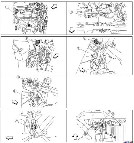
Component Parts Location
1. Power valve actuator 1
2. Intake valve timing control solenoid valve (bank 1)
3. Power steering pressure sensor
4. Intake valve timing control solenoid valve (bank 2)
5. VIAS control solenoid valves 1 and 2
6. Fuel injector (bank 2)
7. Ignition coil (with power transistor) and spark plug (bank 2)
8. Crankshaft position sensor (POS)
9. Engine coolant temperature sensor
10. Camshaft position sensor (PHASE) (bank 2)
11. ECM
12. Refrigerant pressure sensor
13. Battery current sensor
14. PNP switch
15. Condenser-2
16. Mass air flow sensor (with intake air temperature sensor)
17. EVAP service port
18. Camshaft position sensor (PHASE) (bank 1)
19. Electric throttle control actuator
20. Power valve actuator 2
21. EVAP canister purge volume control solenoid valve
22. Ignition coil (with power transistor) and spark plug (bank 1)
23. Knock sensor
1. Mas air flow sensor (with intake air temperature sensor)
2. Air cleaner case
3. Engine coolant temperature sensor
4. EVAP canister purge volume control solenoid valve
5. Power valve actuator 1
6. VIAS control solenoid valve 1
7. VIAS control solenoid valve 2
8. Power valve actuator 2
9. Power steering pressure sensor
10. Tie rod (RH)
11. Power valve actuator 2
12. Camshaft position sensor (PHASE) (bank 1)
13. Camshaft position sensor (PHASE) (bank 2)
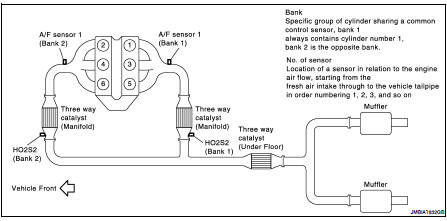
1. A/F sensor 1 (bank 1)
2. A/F sensor 1 (bank 2)
3. HO2S2 (bank 1) harness connector
4. HO2S2 (bank 2) harness connector (CVT models)
5. Front engine mount
6. HO2S2 (bank 2) harness connector (M/T models)
7. Crankshaft position sensor (POS) (M/T models)
8. Crankshaft position sensor (POS) (CVT models)
1. Electronic controlled engine mount control solenoid valve
2. EVAP control system pressure sensor
3. EVAP canister vent control valve
4. EVAP canister
5. Injector harness connector
6. Intake valve timing control solenoid valve (bank 1)
7. Intake valve timing control solenoid valve (bank 2)
1. Knock sensor (bank 2)
2. Knock sensor (bank 1)
3. PNP switch (CVT models)
4. PNP switch (M/T models)
5. Battery
6. IPDM E/R
7. ECM
8. Refrigerant pressure sensor (shown with front grill removed)
9. Accelerator pedal
1. ASCD brake switch
2. Stop lamp switch
3. Brake pedal
4. ASCD steering switch
5. ASCD clutch switch (M/T models)
6. Clutch pedal
Component Description
 Air conditioning cut control
 Can communication