Nissan Altima (L32) 2007-2012 Service Manual: B2098 ignition relay on stuck
Description
• IPDM E/R operates the ignition relay when it receives an ignition switch ON signal from BCM via CAN communication.
• Turn the ignition relay OFF by pressing the push-button ignition switch once when the vehicle speed is 4 km/ h (2.5 MPH) or less.
• Turn the ignition relay OFF with the following operation when the vehicle speed is more than 4 km/h (2.5 MPH) or when an abnormal condition occurs in CAN communication from the unified meter (Emergency OFF) - Press and hold the push-button ignition switch for 2 seconds or more.
- Press the push-button ignition switch 3 time within 1.5 seconds.
NOTE: The ignition relay does not turn ON for 3 seconds after emergency OFF even if the push-button ignition switch is pressed.
DTC Logic
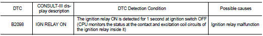
DTC DETECTION LOGIC
Diagnosis Procedure
1. PERFORM SELF DIAGNOSIS
1. Turn the ignition switch ON.
2. Erase “Self Diagnostic Result” of IPDM E/R.
3. Turn ignition switch OFF, and wait for 1 second or more.
4. Turn the ignition switch ON. Check “Self Diagnostic Result” again.
Is “IGN RELAY ON” displayed? YES >> Replace IPDM E/R. Refer to PCS-48, "Removal and Installation".
NO >> Refer to GI-42, "Intermittent Incident".
 U1000 can comm circuit
 B2099 ignition relay off stuck