Nissan Altima (L32) 2007-2012 Service Manual: B2555 stop lamp
Description
BCM detects the stop lamp status and confirms the stop lamp switch ON/OFF status. BCM confirms the engine start condition according to the stop lamp switch ON/OFF status.
DTC Logic
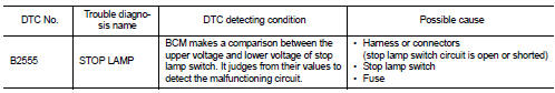
DTC DETECTION LOGIC
DTC CONFIRMATION PROCEDURE
1.PERFORM DTC CONFIRMATION PROCEDURE
1. Depress the brake pedal and wait for at least 1 second.
2. Check “Self diagnostic result” with CONSULT-III.
Is DTC detected? YES >> Refer to SEC-70, "Diagnosis Procedure".
NO >> Inspection End.
Diagnosis Procedure
1.CHECK STOP LAMP SWITCH INPUT SIGNAL
1. Turn ignition switch OFF.
2. Disconnect BCM harness connector.
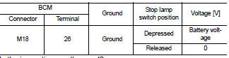
3. Check voltage between BCM harness connector and ground.
Is the inspection result normal? YES >> Stop lamp switch is OK.
NO >> GO TO 2
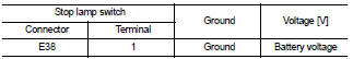
2.CHECK STOP LAMP SWITCH POWER SUPPLY CIRCUIT
1. Disconnect stop lamp switch harness connector.
2. Check voltage between stop lamp harness connector and ground.
Is the inspection result normal? YES >> GO TO 3
NO >> Check harness for open or short between stop lamp switch and fuse.
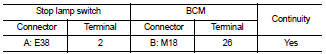
3.CHECK STOP LAMP SWITCH CIRCUIT
1. Check continuity between stop lamp switch harness connector E38 (A) terminal 2 and BCM harness connector M18 (B) terminal 26.
2. Check continuity between stop lamp switch harness connector E38 (A) terminal 2 and ground.
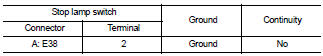
Is the inspection result normal? YES >> GO TO 4
NO >> Repair harness or connector.
4.CHECK STOP LAMP SWITCH
Refer to SEC-71, "Component Inspection".
Is the inspection result normal? YES >> GO TO 5
NO >> Replace stop lamp switch.
5.CHECK INTERMITTENT INCIDENT
Refer to GI-42, "Intermittent Incident".
>> Inspection End.
Component Inspection
1.CHECK STOP LAMP SWITCH
1. Turn ignition switch OFF.
2. Disconnect stop lamp switch harness connector.
3. Check continuity between stop lamp switch terminals under the following conditions.
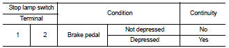
Is the inspection result normal? YES >> Inspection End.
NO >> Replace stop lamp switch.
 B2193, P1612 chain of ecm-immu
 B2556 push-button ignition switch