Nissan Altima (L32) 2007-2012 Service Manual: B2560 starter control relay
Description
Starter control relay, integrated in IPDM E/R, permits the starter relay
operation when in N or P position and
the steering is locked or unlocked. It is installed in parallel with the starter
relay.
DTC Logic
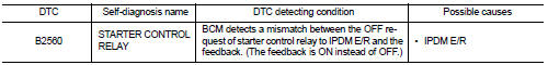
DTC DETECTION LOGIC
NOTE:
• If DTC B2560 is displayed with DTC U1000, first perform the trouble diagnosis
for DTC U1000. Refer to
SEC-235, "DTC Logic".
• If DTC B2560 is displayed with DTC U1010, first perform the trouble diagnosis
for DTC U1010. Refer to
SEC-236, "DTC Logic".
DTC CONFIRMATION PROCEDURE
1.PERFORM DTC CONFIRMATION PROCEDURE
1. Turn ignition switch ON under the following conditions and wait for at
least 2 seconds:
- CVT selector lever is in the P position.
- Depress the brake pedal.
2. Check “Self Diagnostic Result” with CONSULT-III.
Is DTC detected?
YES >> Refer to SEC-274, "Diagnosis Procedure".
NO >> Inspection End.
Diagnosis Procedure
1.CHECK DTC WITH IPDM E/R
Check “Self Diagnostic Result” with CONSULT-III. Refer to PCS-45, "DTC
Index".
Description
BCM receives the 2 vehicle speed signals via CAN communication. One signal is
transmitted by the “unified
meter”. Another signal is transmitted by “ABS actuator and electric uni ...
Description
BCM confirms the shift position with the following 2 signals.
• CVT selector lever
• P position signal from IPDM E/R (CAN)
DTC Logic
DTC DETECTION LOGIC
NOTE:
• If DTC B260 ...
 B2557 vehicle speed
 B2601 shift position