Nissan Altima (L32) 2007-2012 Service Manual: B2606 steering lock relay
Description
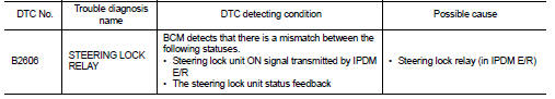
The steering lock relay ON signal is transmitted to IPDM E/R by BCM via CAN
communication.
IPDM E/R turns the steering lock relay ON and transmits the release of the
steering to BCM.
DTC Logic
DTC DETECTION LOGIC
NOTE:
• If DTC B2606 is displayed with DTC U1000, first perform the trouble diagnosis
for DTC U1000. Refer to
SEC-433, "DTC Logic".
• If DTC B2606 is displayed with DTC U1010, first perform the trouble diagnosis
for DTC U1010. Refer to
SEC-434, "DTC Logic".
DTC CONFIRMATION PROCEDURE
1.PERFORM DTC CONFIRMATION PROCEDURE
1. Press the push-button ignition switch under the following conditions.
- CVT selector lever is in the P or N position.
- Do not depress the brake pedal.
2. Steering is locked.
3. Check “Self diagnostic result” with CONSULT-III.
Is DTC detected?
YES >> Refer to SEC-479, "Diagnosis Procedure".
NO >> Inspection End.
Diagnosis Procedure
1.CHECK DTC WITH IPDM E/R
Check “Self diagnostic result” with CONSULT-III. Refer to PCS-45, "DTC
Index".
Is the inspection result normal?
YES >> GO TO 2
NO >> Repair or replace malfunctioning parts.
2.INTERMITTENT INCIDENT
Refer to GI-42, "Intermittent Incident".
>> Inspection End.
Description
BCM confirms the shift position with the following 4 signals.
• CVT selector lever
• P/N position switch
• P position signal from IPDM E/R (CAN)
• P position signal from TC ...
Description
BCM requests to IPDM E/R to supply power to electronic steering column lock.
IPDM E/R sends status of
electronic steering column lock back to BCM.
DTC Logic
DTC DETECTION LOGIC
NOT ...
Other materials: Child safety
WARNING
Do not allow children to play with the
seat belts. Most seating positions are
equipped with Automatic Locking Retractor
(ALR) mode seat belts. If the seat
belt becomes wrapped around a child’s
neck with the ALR mode activated, the
child can be seriously injured or killed if
the seat belt r ...
Settings
The setting mode allows you to change the
information displayed in the vehicle information
display. It also allows you to change
vehicle functions:
VDC
Driver Assistance
Clock
Meter Settings
Vehicle Settings
Maintenance
Alarm
Tire Pressures
Unit
Language
Factory Reset
VDC
The VDC Settin ...
Oil control system (if so equipped)
The oil control system can be accessed in
the Maintenance portion of the vehicle information
display settings.
Engine oil information informs the distance
to oil change. Never exceed one year or
7,500 miles (12000 km) between oil change
intervals for the 2.0L 4 cylinder (KR20DDET
engine model) or 1 ...
 B2605 PNP switch
 B2607 steering lock relay