Nissan Altima (L32) 2007-2012 Service Manual: B2612 steering status
Description
There are 2 switches in the steering unit. IPDM E/R compares those 2 switches conditions to judge the present steering status and transmit the result to BCM via CAN communication.
DTC Logic
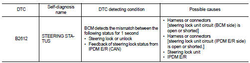
DTC DETECTION LOGIC
NOTE: • If DTC B2612 is displayed with DTC U1000, first perform the trouble diagnosis for DTC U1000. Refer to SEC-36, "DTC Logic".
• If DTC B2612 is displayed with DTC U1010, first perform the trouble diagnosis for DTC U1010. Refer to SEC-37, "DTC Logic".
DTC CONFIRMATION PROCEDURE
1.PERFORM DTC CONFIRMATION PROCEDURE 1
1. Press the push-button ignition switch under the following conditions and wait for at least 1 second.
- CVT selector lever is in the P or N position.
- Do not depress brake pedal.
- Steering is locked.
2. Check “Self diagnostic result” with CONSULT-III.
Is DTC detected? YES >> Refer to SEC-101, "Diagnosis Procedure".
NO >> GO TO 2
2.PERFORM DTC CONFIRMATION PROCEDURE 2
1. Turn ignition switch ON.
2. Turn ignition switch OFF.
3. Press door switch.
4. Check “Self diagnostic result” with CONSULT-III.
Is DTC detected? YES >> Refer to SEC-101, "Diagnosis Procedure".
NO >> Inspection End.
Diagnosis Procedure
1.INSPECTION START
Check the case in which DTC is detected.
• Case1: It is detected after ignition switch is changed from ON to OFF and door switch is pressed.
• Case2: It is detected after ignition switch is changed from ON to OFF In which case is DTC detected? Case1 >> GO TO 2
Case2 >> GO TO 7
2.CHECK BCM OUTPUT SIGNAL
1. Turn ignition switch OFF.
2. Disconnect steering lock unit harness connector and IPDM E/R harness connector.
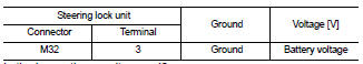
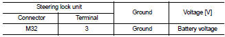
3. Check voltage between steering lock unit harness connector and ground.
Is the inspection result normal? YES >> GO TO 4
NO >> GO TO 3
3.CHECK STEERING LOCK UNIT CIRCUIT-I
1. Disconnect BCM harness connector.
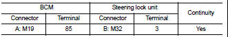
2. Check continuity between BCM harness connector M19 (A) terminal 85 and steering lock unit harness connector M32 (B) terminal 3.
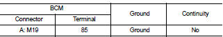
3. Check continuity between BCM harness connector M19 (A) terminal 85 and ground.
Is the inspection result normal? YES >> GO TO 6
NO >> Repair harness or connector.
4.CHECK IPDM E/R OUTPUT SIGNAL
1. Connect IPDM E/R harness connector.
2. Disconnect BCM harness connector.
3. Check voltage between steering lock unit harness connector and ground.
Is the inspection result normal? YES >> Replace steering lock unit.
NO >> GO TO 5
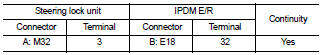
5.CHECK STEERING LOCK UNIT CIRCUIT-II
1. Check continuity between steering lock unit harness connector M32 (A) terminal 3 and IPDM E/R harness connector E18 (B) terminal 32.
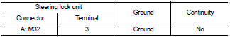
2. Check continuity between steering lock unit harness connector M32 (A) terminal 3 and ground.
Is the inspection result normal? YES >> GO TO 6
Is the inspection result normal? YES >> GO TO 6
6.CHECK INTERMITTENT INCIDENT
Refer to GI-42, "Intermittent Incident".
>> Inspection End.
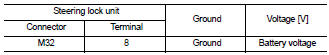
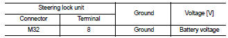
7.CHECK BCM OUTPUT SIGNAL
1. Turn ignition switch OFF.
2. Disconnect steering lock unit harness connector and IPDM E/R harness connector.
3. Check voltage between steering lock unit harness connector and ground.
Is the inspection result normal? YES >> GO TO 9
NO >> GO TO 8
8.CHECK STEERING LOCK UNIT CIRCUIT-I
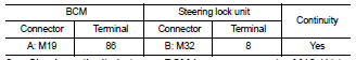
1. Disconnect BCM harness connector.
2. Check continuity between BCM harness connector M19 (A) terminal 86 and steering lock unit harness connector M32 (B) terminal 8.
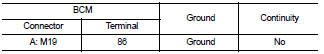
3. Check continuity between BCM harness connector M19 (A) terminal 86 and ground.
Is the inspection result normal?
YES >> GO TO 11
NO >> Repair harness or connector.
9.CHECK IPDM E/R OUTPUT SIGNAL
1. Connect IPDM E/R harness connector.
2. Disconnect BCM harness connector.
3. Check voltage between steering lock unit harness connector and ground.
Is the inspection result normal? YES >> Replace steering lock unit.
NO >> GO TO 10
10.CHECK STEERING LOCK UNIT CIRCUIT-II
1. Check continuity between steering lock unit harness connector M32 (A) terminal 8 and IPDM E/R harness connector E18 (B) terminal 33.
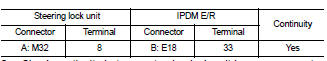
2. Check continuity between steering lock unit harness connector and ground.
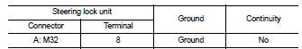
Is the inspection result normal? YES >> GO TO 11
NO >> Repair harness or connector.
11.CHECK INTERMITTENT INCIDENT
Refer to GI-42, "Intermittent Incident".
>> Inspection End.
 B260f engine status
 B2617 starter relay circuit