Nissan Altima (L32) 2007-2012 Service Manual: B terminal circuit
Description
The “B” terminal is constantly supplied with battery power.
Diagnosis Procedure
CAUTION: Perform diagnosis under the condition that the engine cannot start by the following procedure.
1. Remove fuel pump fuse.
2. Crank or start the engine (where possible) until the fuel pressure is depleted.
1.CHECK TERMINAL B POWER SUPPLY VOLTAGE
1. Turn ignition switch OFF.
2. Make sure that starter motor connector F27 terminal B connection is clean and tight.
3. Check voltage between starter motor connector F27 terminal B and ground.

Is there battery voltage present? YES >> GO TO 2
NO >> Check harness between battery and starter motor for open circuit.
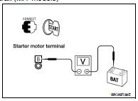
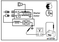
2.CHECK BATTERY CABLE (VOLTAGE DROP TEST)
1. Shift CVT selector lever to “P” or “N” position. (CVT models) Press and hold the clutch pedal fully with the control lever in neutral. (M/T models) 2. Check voltage between battery positive terminal and starter motor connector F27 terminal B while cranking the engine.
Is the voltage drop less than 0.5V? YES >> GO TO 3
NO >> Check harness between the battery and the starter motor for high resistance.
3.CHECK GROUND CIRCUIT STATUS (VOLTAGE DROP TEST)
1. Shift CVT selector lever to “P” or “N” position. (CVT models) Press and hold the clutch pedal fully with the control lever in neutral. (M/T models) 2. Check voltage between starter motor case and battery negative terminal while cranking the engine.

Is the voltage drop less than 0.2V? YES >> Terminal B circuit is OK. Further inspection necessary.
Refer to STR-29, "Work Flow".
NO >> Check the starter motor case to engine mounting for high resistance.
 Component diagnosis
 S connector circuit