Nissan Altima (L32) 2007-2012 Service Manual: BCM
Diagnosis Procedure
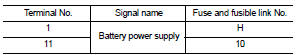
1. CHECK FUSE AND FUSIBLE LINK
Check if the following BCM fuse or fusible link are blown.
Is the fuse or fusible link blown?
YES >> Replace the blown fuse or fusible link after repairing the affected
circuit.
NO >> GO TO 2
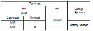
2. CHECK POWER SUPPLY CIRCUIT
1. Turn ignition switch OFF.
2. Disconnect BCM.
3. Check voltage between BCM harness connector and ground.
Is the measurement normal?
YES >> GO TO 3
NO >> Repair or replace harness.
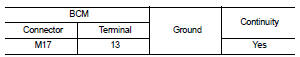
3. CHECK GROUND CIRCUIT
Check continuity between BCM harness connector and ground.
Does continuity exist?
YES >> Inspection End.
NO >> Repair or replace harness.
Special Repair Requirement
1. REQUIRED WORK WHEN REPLACING BCM
Initialize control unit. Refer to BCS-6, "CONFIGURATION (BCM) : Special
Repair Requirement".
>> Work End.
Diagnosis Procedure
1. CHECK FUSES AND FUSIBLE LINK
Check that the following IPDM E/R fuses or fusible link are not blown.
Is the fuse blown?
YES >> Replace the blown fuse or fusible link ...
Other materials: How to use the vehicle information
display
The vehicle information display can be
changed using the ,
, and OK buttons located on the
steering
wheel.
- Use these buttons
to navigate the vehicle information
display.
OK - Change or select an item in the
vehicle information display.
- Returns to the previous
menu.
The OK, and
butto ...
Resetting the drive computer
The drive computer is divided across three
screens:
Speed
Trip Distance & Time
Fuel Economy
1. Press the or
buttons until the
desired drive computer screen is
displayed.
2. Press the OK button to bring up the drive
computer Reset menu.
3. Use the or
to select the desired
option. Then press ...
Seat belt warning light and chime
The driver and front passenger seat is
equipped with an enhanced seat belt reminder
function.
A visual and audible alert will operate at
speeds of approximately 9 mph (15 km/h)
or more under the following conditions:
If the driver seat belt is not fastened.
The front passenger’s seat belt is ...
 Power supply and ground circuit
 IPDM E/R (intelligent power distribution
module engine room)
IPDM E/R (intelligent power distribution
module engine room)