Nissan Altima (L32) 2007-2012 Service Manual: BCM (Body control module)
Reference Value
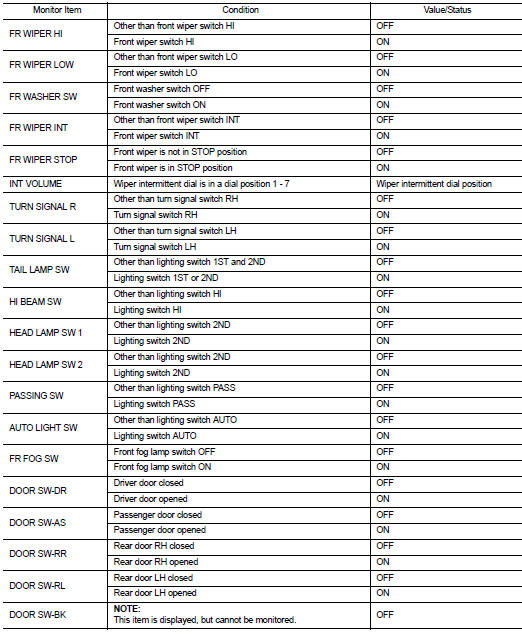
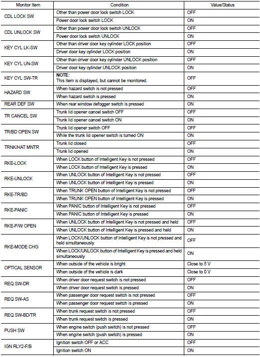
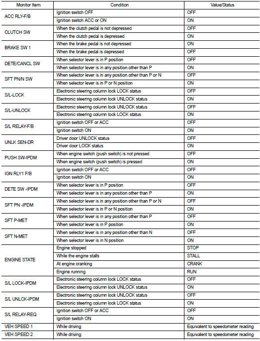
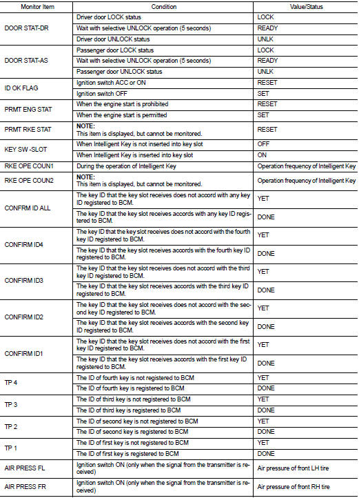
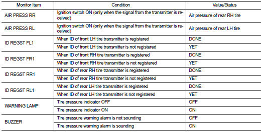
VALUES ON THE DIAGNOSIS TOOL
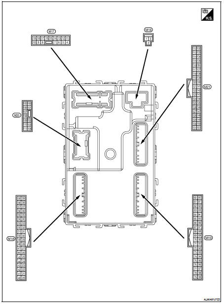
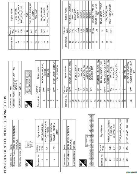
Terminal Layout
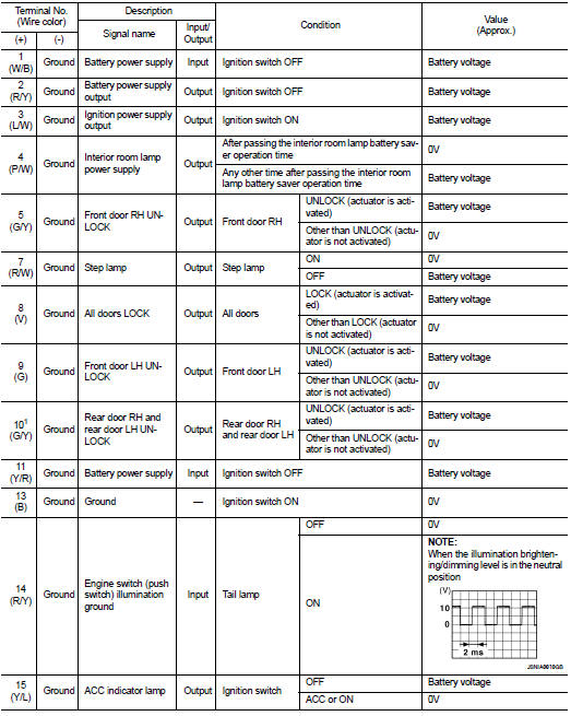
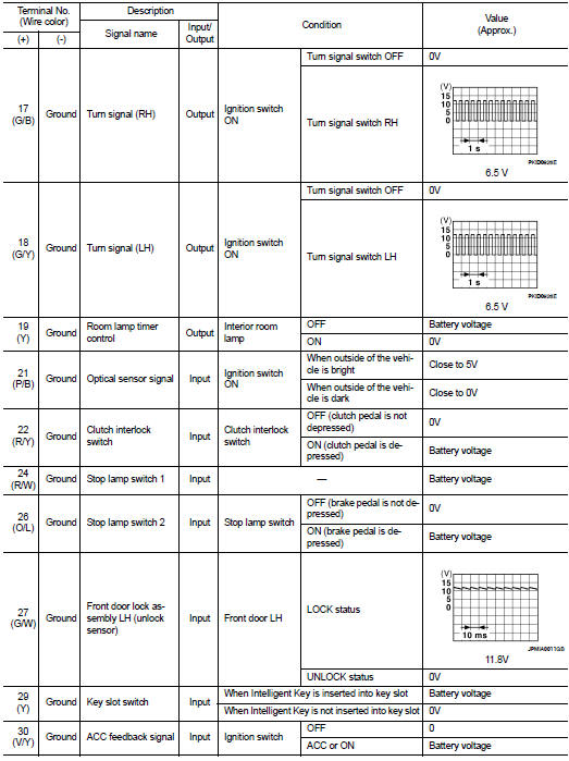
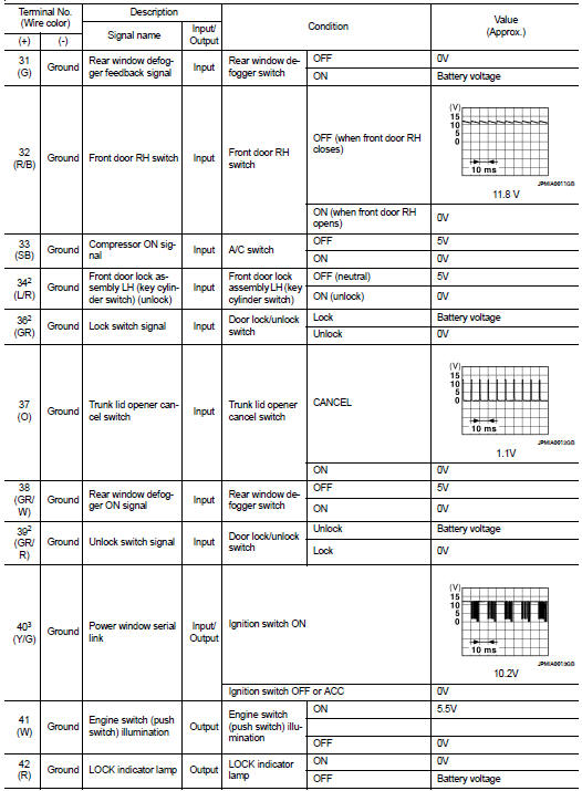
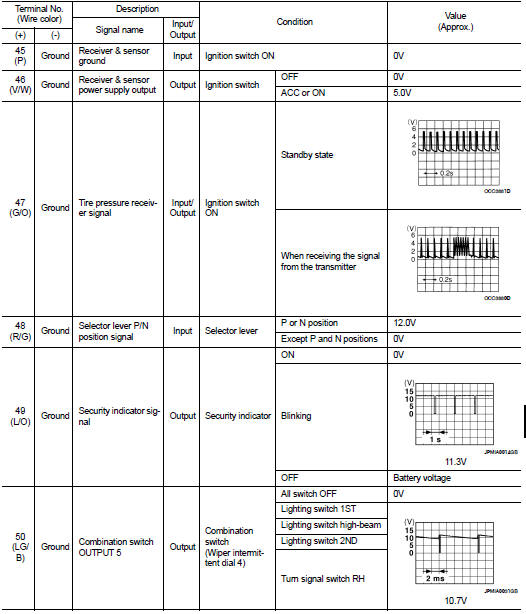
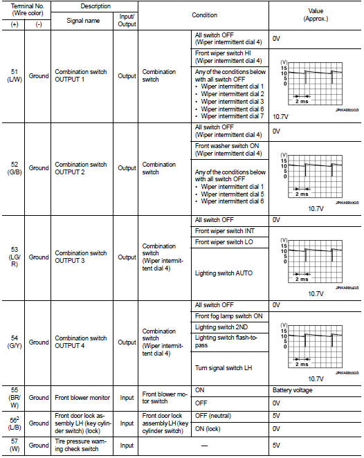
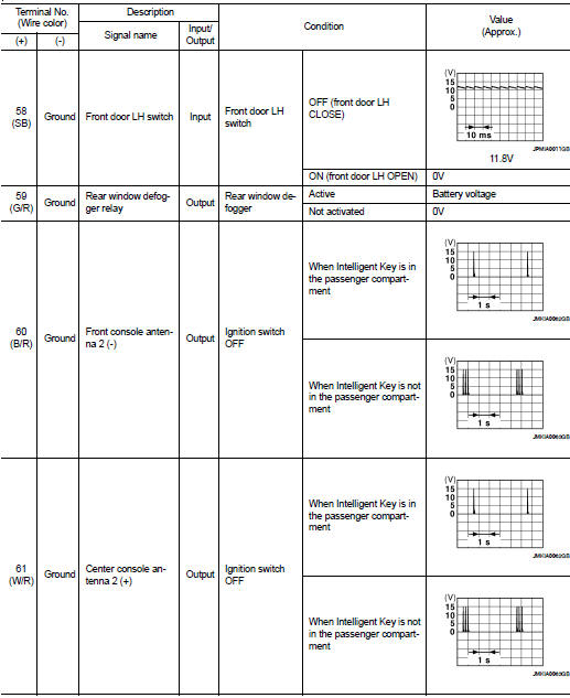
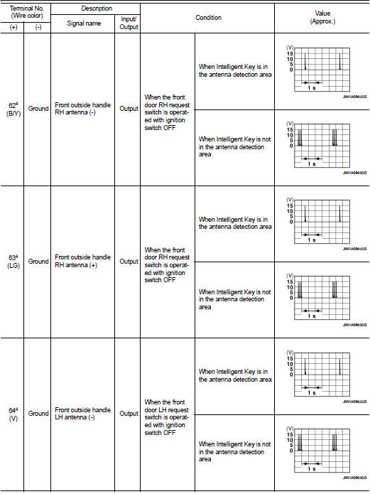
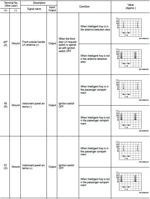
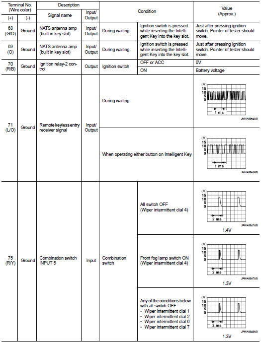
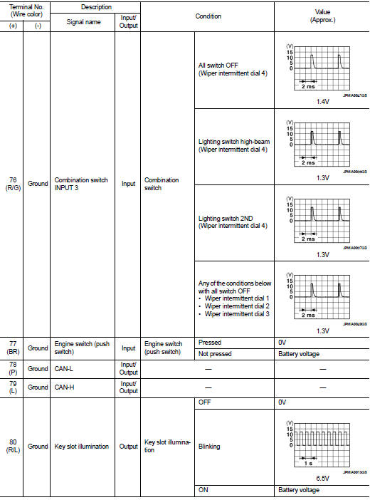
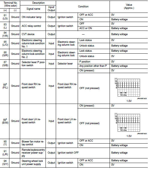
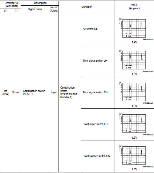
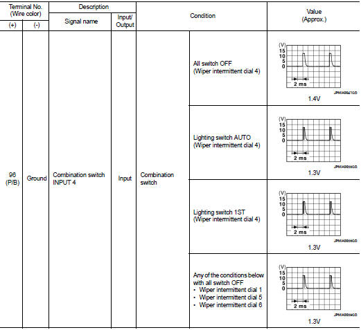
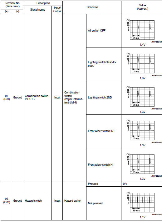
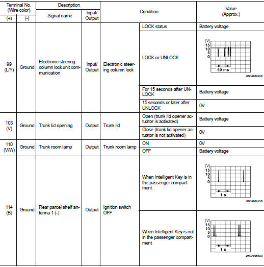
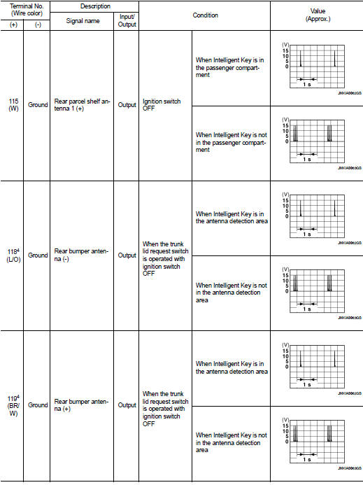
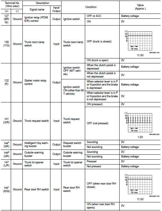
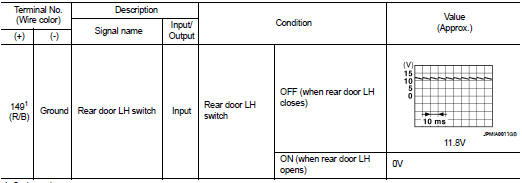
Physical Values
1: Sedan only
2: With LH front window anti-pinch
3: With LH and RH front window anti-pinch
4: With Intelligent Key
5: Without Intelligent Key
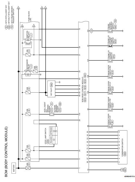
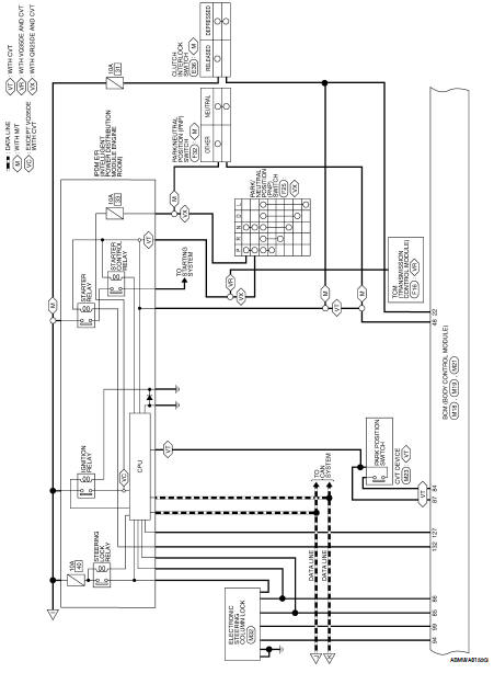
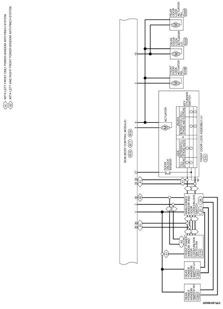
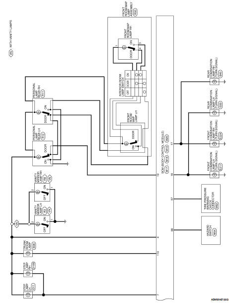
Wiring Diagram-Sedan
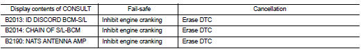
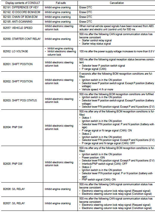
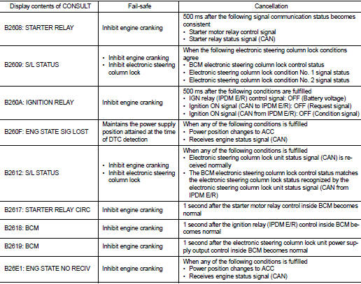
Fail Safe
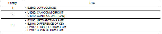
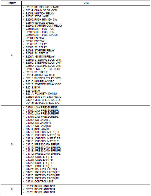
DTC Inspection Priority Chart
If some DTCs are displayed at the same time, perform inspections one by one
based on the following priority
chart.
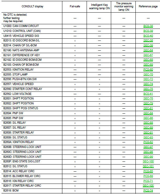
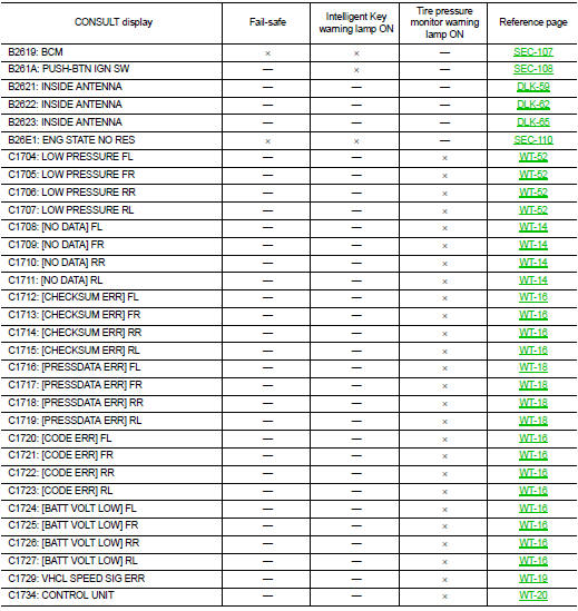
DTC Index
NOTE:
Details of time display
• CRNT: Displays when there is a malfunction now or after returning to the
normal condition until turning ignition
switch OFF → ON again.
• 1 - 39: Displayed if any previous malfunction is present when current
condition is normal. It increases like 1
→ 2 → 3...38 → 39 after returning to the normal condition whenever ignition
switch OFF → ON. The counter
remains at 39 even if the number of cycles exceeds it. It is counted from 1
again when turning ignition switch
OFF → ON after returning to the normal condition if the malfunction is detected
again.
Reference Value
TERMINAL LAYOUT
PHYSICAL VALUES
POWER WINDOW AND DOOR LOCK/UNLOCK SWITCH RH
Wiring Diagram
Fail Safe
FAIL-SAFE CONTROL
Switches to fail-safe control when ...
Precaution for Supplemental Restraint System
(SRS) "AIR BAG" and "SEAT BELT PRE-TENSIONER"
The Supplemental Restraint System such as “AIR BAG” and “SEAT BELT PRE-TENSIONERâ ...
 Front power window switch
 Precaution