Nissan Altima (L32) 2007-2012 Service Manual: Front power window switch
Reference Value
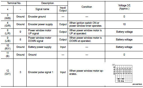
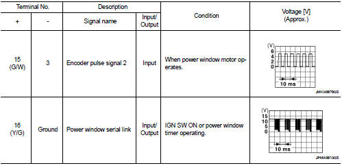
TERMINAL LAYOUT
PHYSICAL VALUES
POWER WINDOW AND DOOR LOCK/UNLOCK SWITCH RH
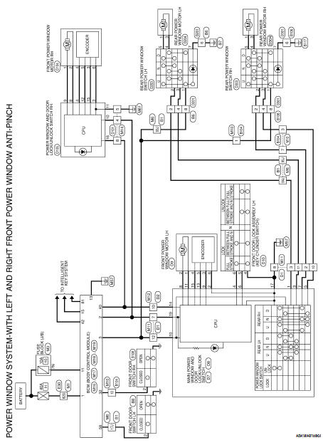
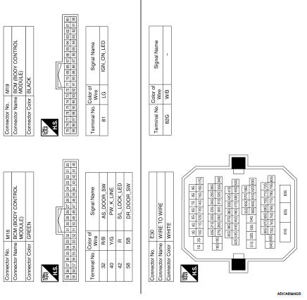
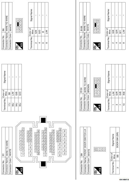
Wiring Diagram
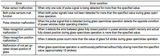
Fail Safe
FAIL-SAFE CONTROL
Switches to fail-safe control when malfunction is detected in encoder signal
that detects up/down speed and
direction of door glass. Switches to fail-safe control when error beyond
regulation value is detected between
the fully closed position and the actual position of the glass.
It changes to condition before initialization and the following functions do
not operate when switched to failsafe
control.
• Auto-up operation
• Anti-pinch function
• Retained power function
Perform initial operation to recover when switched to fail-safe mode.
However, it switches back to fail-safe
control when malfunction is found in power window switch or in motor.
Reference Value
TERMINAL LAYOUT
PHYSICAL VALUES
MAIN POWER WINDOW AND DOOR LOCK/UNLOCK SWITCH
Wiring Diagram
Fail Safe
FAIL-SAFE CONTROL
Switches to fail-safe control wh ...


 Power window main switch
 BCM (Body control module)