Nissan Altima (L32) 2007-2012 Service Manual: Body control system
System Description
OUTLINE
• BCM (body control module) controls the various electrical components. It inputs the information required to the control from CAN communication and the signal received from each switch and sensor.
• BCM has combination switch reading function for reading the operation status of combination switches (light, turn signal, wiper and washer) in addition to a function for controlling the operation of various electrical components.
It also has the signal transmission function as the passed point of signal and the power saving control function that reduces the power consumption with the ignition switch OFF.
• BCM is equipped with the diagnosis function that performs the diagnosis with CONSULT-III and various settings.
CAN communication control
In CAN communication, control units are connected with 2 communication lines (CAN-L, CAN-H) allowing a high rate of information transmission with less wiring. Each control unit transmits/receives the data but selectively reads required information only.
CAN communication signal
Refer to the LAN-25, "CAN Communication Signal Chart".
BCM control function list
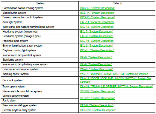
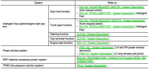
Component Parts Location
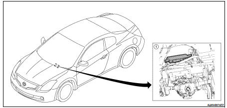
1. BCM M16, M17, M18, M19, M20, M21 (view with instrument panel removed) (coupe shown, sedan similar)
 Function diagnosis
 Combination switch reading system