Nissan Altima (L32) 2007-2012 Service Manual: Control linkage
Exploded View
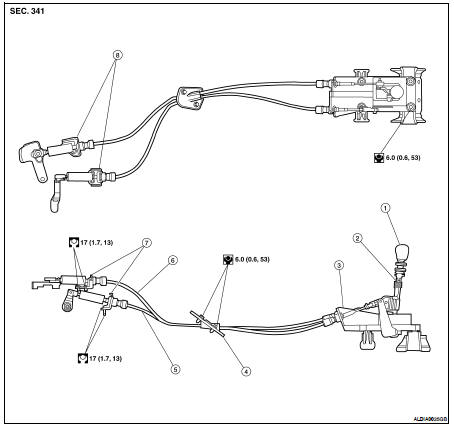
1. Control lever knob
2. Control lever
3. Control device assembly
4. Retainer grommet
5. Select cable
6. Shift cable
7. Lock plate
8. Cable bracket
Removal and Installation
REMOVAL
1. Shift control lever to the neutral position.
2. Remove the air filter assembly. Refer to EM-25, "Removal and Installation" (QR25DE), EM-129, "Removal and Installation" (VQ35DE).
3. Remove the shift cable from the shift lever and cable bracket.
4. Remove the select cable from the select lever and cable bracket.
5. Remove the center console. Refer to IP-18, "Disassembly and Assembly".
6. Remove the shift cable from the control device assembly.
7. Remove the select cable from the control device assembly.
8. Remove the bracket covering the retainer grommet.
9. Remove the retainer grommet bolts and retainer grommet.
10. Remove the shift cable and select cable from the vehicle.
11. Remove the control device assembly bolts and the control device assembly.
INSTALLATION
Installation is in the reverse order of removal.
• After assembly, make sure control lever automatically returns to Neutral when it is moved to 1st, 2nd, or Reverse.
• When control lever is shifted to each position, make sure there is no binding or disconnection at each connection.
Adjustment
SELECT CABLE ADJUSTMENT
1. Remove the select cable eye end (1) from the select lever (2) of the control device.
2. Slide the lock (A) on the select cable eye end (1) away from the cable end.
3. Turn the select cable eye end (1) over and push the stopper (B) to release the adjustment.
4. Install the select cable eye end (1) to the select lever (2) of the control device
5. Hold the shift lever with the gap between the reverse gate stopper and the shifter base at the specified distance (A).

6. Push the stopper (B) into the cable eye end housing (1).
7. Slide the lock (A) over the stopper (B).
8. Check for smooth gear select operation.
 Park/neutral position switch
 Air breather hose