Nissan Altima (L32) 2007-2012 Service Manual: Cooling fan
Description
The ECM controls the cooling fan corresponding to the vehicle speed, engine colant temperature, refrigerant pressure, and air conditioner ON signal. The control system has 4-step control [HIGH/MIDDLE/LOW/OFF].
COOLING FAN MOTOR
The cooling fan operates at each speed when the current flows in the cooling fan motor as follows.
The cooling fan operates at low (LOW) speed when cooling fan motors-1 and -2 are circuited in series and middle speed condition.
Refer to EC-77, "System Diagram".
Component Function Check
1.CHECK COOLING FAN FUNCTION

1. Turn ignition switch ON.
2. Perform “COOLING FAN” in “ACTIVE TEST” mode with CONSULT-III.
3. Touch “LOW”“MID” “Hi” on the CONSULT-III screen.
4. Check that cooling fan operates.

1. Perform IPDM E/R auto active test and check cooling fan motors operation, refer to PCS-14, "Diagnosis Description".
2. Check that cooling fan operates.
Is the inspection result normal? YES >> INSPECTION END
NO >> Refer to EC-456, "Diagnosis Procedure".
Diagnosis Procedure
1.CHECK COOLING FAN RELAY POWER SUPPLY CIRCUIT
1. Turn ignition switch OFF.
2. Disconnect cooling fan relays-2, -3.
3. Turn ignition switch ON.
4. Check the voltage between cooling fan relays-2, -3 harness connectors and ground.
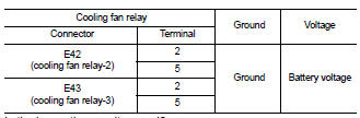
Is the inspection result normal?
YES >> GO TO 3.
NO >> GO TO 2.
2.DETECT MALFUNCTIONING PART
Check the following.
• 10 A fuse (No. 33)
• 40 A fusible link (letter K)
• IPDM E/R harness connector E18
• Harness for open or short between cooling fan relay-2 and battery
• Harness for open or short between cooling fan relay-3 and battery
• Harness for open or short between cooling fan relay-2 and IPDM E/R
• Harness for open or short between cooling fan relay-3 and IPDM E/R
>> Repair open circuit, short to ground or short to power in harness or connectors.
3.CHECK COOLING FAN RELAY OUTPUT SIGNAL CIRCUIT
1. Turn ignition switch OFF.
2. Disconnect IPDM E/R harness connectors.
3. Check the continuity between cooling fan relay-2, -3 harness connectors and IPDM E/R harness connector.
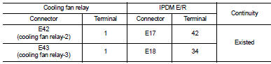
4. Also check harness for short to ground and short to power.
Is the inspection result normal? YES >> GO TO 5.
NO >> GO TO 4.
4.DETECT MALFUNCTIONING PART
Check the following.
• Harness for open or short between cooling fan relay-2 and IPDM E/R
• Harness for open or short between cooling fan relay-3 and IPDM E/R
>> Repair open circuit, short to ground or short to power in harness or connectors.
5.CHECK COOLING FAN MOTOR POWER SUPPLY CIRCUIT
1. Disconnect cooling fan motor-1 harness connector.
2. Check the voltage between cooling fan motor-1 harness connector and ground.
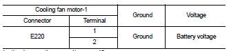
Is the inspection result normal? YES >> GO TO 7.
NO >> GO TO 6.
6.DETECT MALFUNCTIONING PART
Check the following.
• 40 A fusible link (letter M) • Harness connector E12, E203
• Harness for open or short between cooling fan motor-1 and battery
>> Repair open circuit, short to ground or short to power in harness or connectors.
7.CHECK COOLING FAN MOTOR CIRCUIT-I
1. Disconnect cooling fan motor-2 harness connector.
2. Check the continuity between cooling fan relay-2, -3 harness connectors and cooling fan motor-1, -2 harness connectors.
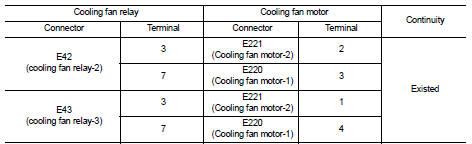
3. Also check harness for short to ground and short to power.
Is the inspection result normal? YES >> GO TO 9.
NO >> GO TO 8.
8.DETECT MALFUNCTIONING PART
Check the following.
• Harness connector E12, E203
• Harness for open or short between cooling fan motor-1 and cooling fan relay-2
• Harness for open or short between cooling fan motor-1 and cooling fan relay-3
• Harness for open or short between cooling fan motor-2 and cooling fan relay-2
• Harness for open or short between cooling fan motor-2 and cooling fan relay-3
>> Repair open circuit, short to ground or short to power in harness or connectors.
9.CHECK COOLING FAN MOTOR CIRCUIT-II
1. Check the continuity between IPDM E/R harness connector and cooling fan motor-1, -2 harness connector.
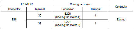
2. Also check harness for short to ground and short to power.
Is the inspection result normal? YES >> GO TO 11.
NO >> GO TO 10.
10.DETECT MALFUNCTIONING PART
Check the following.
• Harness connector E12, E203
• Harness for open or short between cooling fan motor-1 and IPDM E/R
• Harness for open or short between cooling fan motor-2 and IPDM E/R
>> Repair open circuit, short to ground or short to power in harness or connectors.
11.CHECK COOLING FAN MOTOR CIRCUIT-III
1. Check the continuity between cooling fan relay-2, -3 harness connectors and ground.
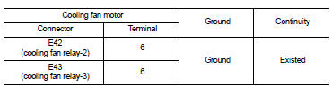
2. Also check harness for short to ground and short to power.
Is the inspection result normal? YES >> GO TO 12.
NO >> Repair open circuit, short to ground or short to power in harness or connectors.
12.CHECK COOLING FAN MOTOR CIRCUIT-IV
1. Check the continuity between cooling fan motor-2 harness connector and ground.
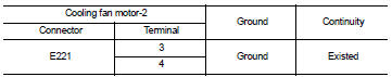
2. Also check harness for short to ground and short to power.
Is the inspection result normal? YES >> GO TO 13.
NO >> Repair open circuit, short to ground or short to power in harness or connectors.
13.CHECK COOLING FAN RELAY-2 AND -3
Refer to EC-460, "Component Inspection (Cooling Fan Relay)".
Is the inspection result normal? YES >> GO TO 14.
NO >> Replace malfunctioning cooling fan relay.
14.CHECK COOLING FAN MOTORS-1 AND -2
Refer to EC-459, "Component Inspection (Cooling Fan Motor)".
Is the inspection result normal? YES >> GO TO 15.
NO >> Replace malfunctioning cooling fan motor.
15.CHECK INTERMITTENT INCIDENT
Perform GI-42, "Intermittent Incident".
Is the inspection result normal? YES >> Replace IPDM E/R.
NO >> Repair or replace harness connectors.
Component Inspection (Cooling Fan Motor)
1.CHECK COOLING FAN MOTOR
1. Turn ignition switch OFF.
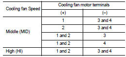
2. Disconnect cooling fan motor harness connector.
3. Supply cooling fan motor terminals with battery voltage and check operation.
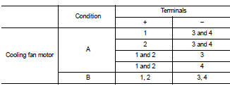
Check that cooling fan speed of condition B is higher than that of A.
Is the inspection result normal? YES >> INSPECTION END NO >> Replace cooling fan motor.
Component Inspection (Cooling Fan Relay)
1.CHECK COOLING FAN RELAYS
1. Turn ignition switch OFF.
2. Remove cooling fan relay.
3. Check the continuity between cooling fan relay terminals under the following conditions.
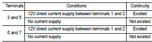
Is the inspection result normal? YES >> INSPECTION END
NO >> Replace cooling fan relay.
 ASCD indicator
 Electrical load signal