Nissan Altima (L32) 2007-2012 Service Manual: Diagnosis and repair workflow
Work Flow
OVERALL SEQUENCE
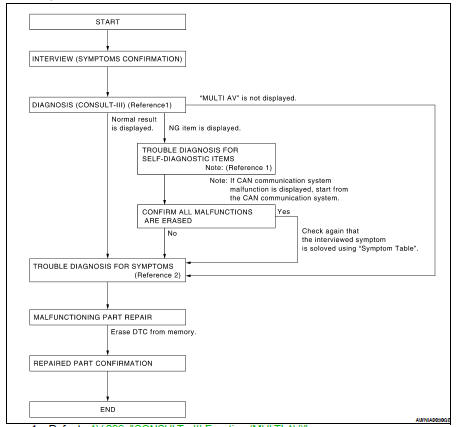
• Reference 1··· Refer to AV-289, "CONSULT - III Function (MULTI AV)".
• Reference 2··· Refer to AV-424, "Symptom Table".
DETAILED FLOW
1.CHECK SYMPTOM
Check the malfunction symptoms by performing the following items.
• Interview the customer to obtain the malfunction information (conditions and environment when the malfunction occurred).
• Check the symptom.
>> GO TO 2
2.SELF-DIAGNOSIS (CONSULT-III)
1. Connect CONSULT-III and perform “SELF-DIAGNOSIS” for “MULTI AV”.
NOTE: Skip to step 4 of the diagnosis procedure if “MULTI AV” is not displayed.
2. Check if any DTC No. is displayed in the self-diagnosis results.
Is any DTC No. displayed? YES >> GO TO 3
NO >> GO TO 4
3.CHECK SELF-DIAGNOSIS RESULTS (CONSULT-III)
1. Check the DTC No. indicated in the self-diagnosis results.
2. Perform the relevant diagnosis referring to the DTC No. list. Refer to AV-389, "DTC Index".
NOTE: Start with the diagnosis for the CAN communication system if “CAN COMM CIRCUIT [U1000] or CONTROL UNIT (CAN) [U1010]” is displayed.
>> GO TO 5
4.PERFORM DIAGNOSIS BY SYMPTOM
Perform the relevant diagnosis referring to the diagnosis chart by symptom. Refer to AV-424, "Symptom Table".
>> GO TO 5
5.REPAIR OR REPLACE MALFUNCTIONING PARTS
Repair or replace the identified malfunctioning parts.
NOTE: Erase the stored self-diagnosis results after repairing or replacing the relevant components if any DTC No. has been indicated in the self-diagnosis results.
>> GO TO 6
6.CHECK AFTER REPAIR
1. Perform self-diagnosis for “MULTI AV” with CONSULT-III after repairing or replacing the malfunctioning parts.
2. Check if any DTC No. is displayed in the self-diagnosis results.
Is any DTC No. displayed? YES >> GO TO 3
NO >> GO TO 7
7.FINAL CHECK
Perform the operation check to confirm that the malfunction symptom is solved or that any other symptoms are present.
Are any symptoms present? YES >> GO TO 4
NO >> Inspection End.
 Basic inspection
 Inspection and adjustment