Nissan Altima (L32) 2007-2012 Service Manual: ECU diagnosis
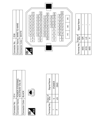
POWER STEERING CONTROL UNIT
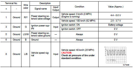
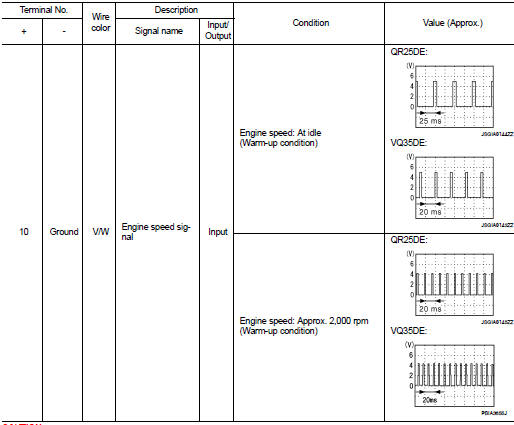
Reference Value
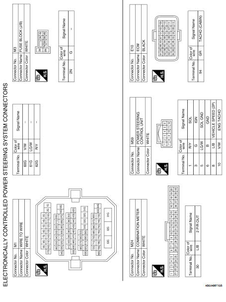
TERMINAL LAYOUT
PHYSICAL VALUES
CAUTION:
When using circuit tester or oscilloscope to measure voltage for inspection, be
sure not to extend forcibly any connector terminals.
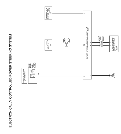
Wiring Diagram — ELECTRONICALLY CONTROLLED
POWER STEERING SYSTEM
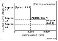
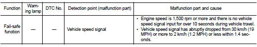
Fail Safe
EPS system
• EPS system enters the fail-safe mode (that allows the steering
force to be controlled without impairing the drive ability) if any of
the input/output signals to/from EPS system (power steering control
unit) deviate from the standard.
NOTE:
The system enters the fail-safe mode if the engine speed remains
at 1,500 rpm or more for over 10 seconds while the vehicle is
stopped. This is normal.
• The fail-safe function is canceled when a vehicle speed signal of 2
km/h (1.2 MPH) or more is inputted or the key switch is turned
OFF→ ON. EPS system restores the normal operation at that time.
Description
• Combination meter sends vehicle speed signal to power steering control
unit.
Diagnosis Procedure
1.PERFORM COMBINATION METER SELF-DIAGNOSIS
Perform combination meter self-diagno ...
UNBALANCE STEERING WHEEL TURNING
FORCE (TORQUE VARIATION)
Description
• Hard steering when fully turning the steering wheel.
• Light steering when driving at a high speed.
Diagnosis Proce ...

 Vehicle speed signal circuit
 Symptom diagnosis