Nissan Altima (L32) 2007-2012 Service Manual: ECU Diagnosis
ECM
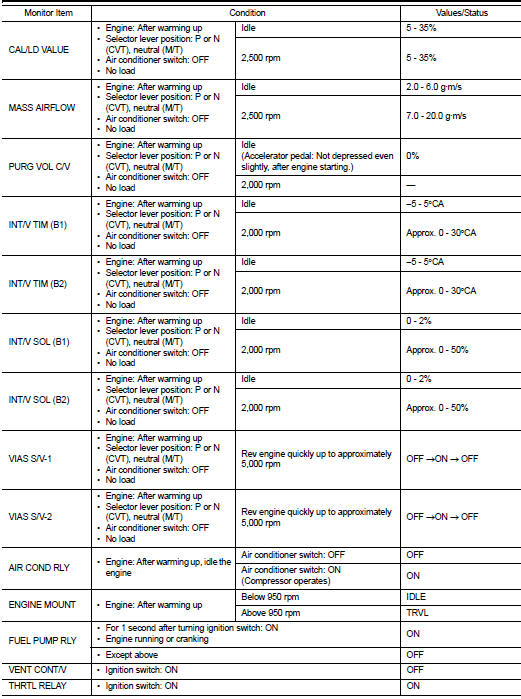
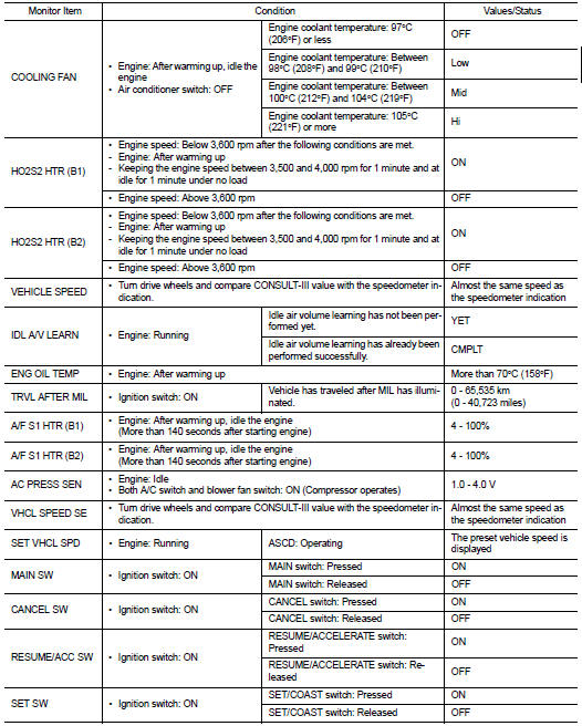
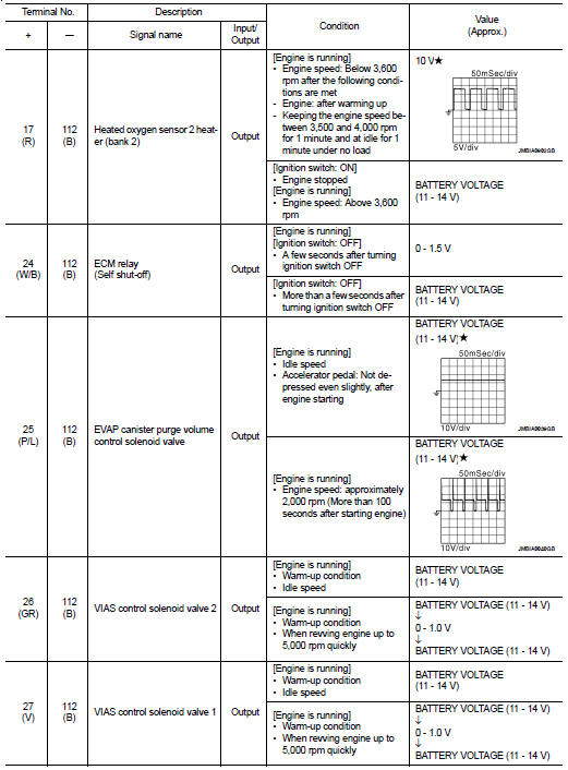
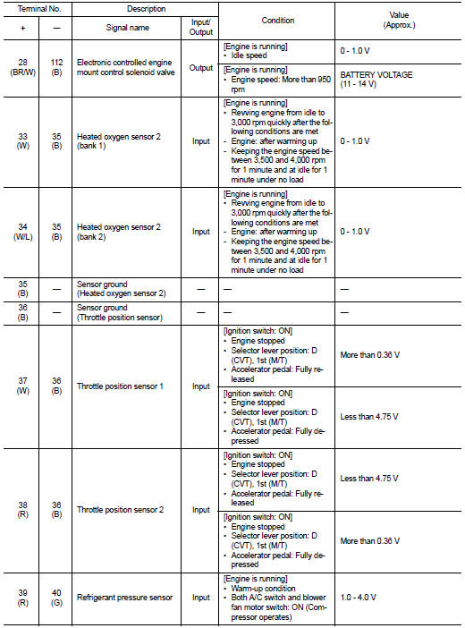
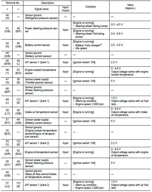
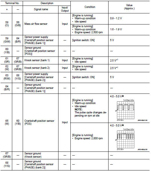
Reference Value
VALUES ON THE DIAGNOSIS TOOL
Remarks: ● Specification data are reference values.
● Specification data are output/input values which are detected or supplied by the ECM at the connector.
* Specification data may not be directly related to their components signals/values/operations.
I.e. Adjust ignition timing with a timing light before monitoring IGN TIMING, because the monitor may show the specification data in spite of the ignition timing not being adjusted to the specification data. This IGN TIMING monitors the data calculated by the ECM according to the signals input from the camshaft position sensor and other ignition timing related sensors.
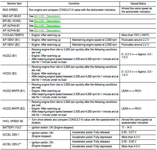
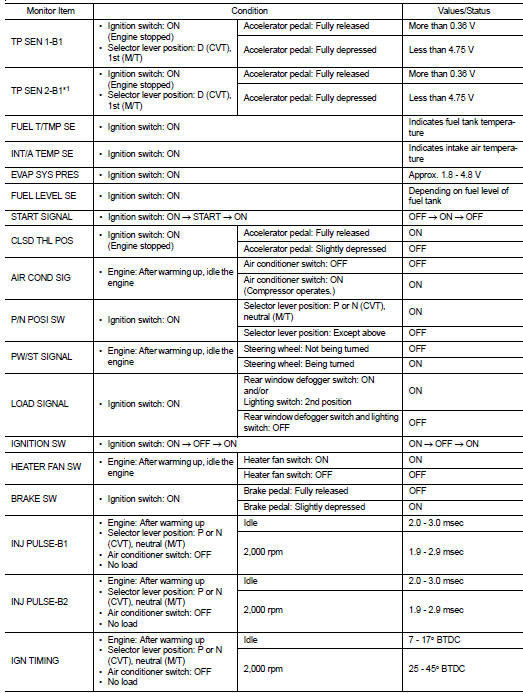
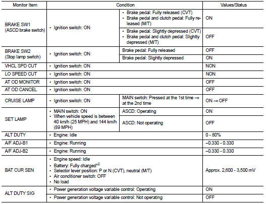
*1: Accelerator pedal position sensor 2 signal and throttle position sensor 2 signal are converted by ECM internally. Thus, they differ from ECM terminals voltage signal.
*2: Before measuring the terminal voltage, confirm that the battery is fully charged. Refer to PG-3, "How to Handle Battery".
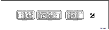
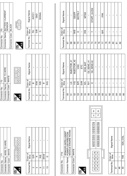
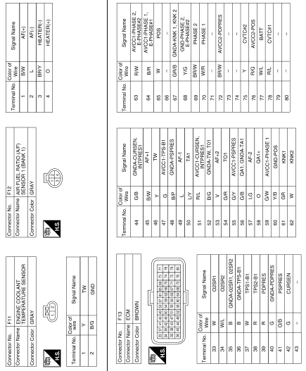
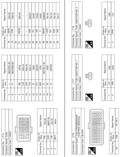
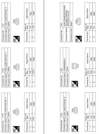
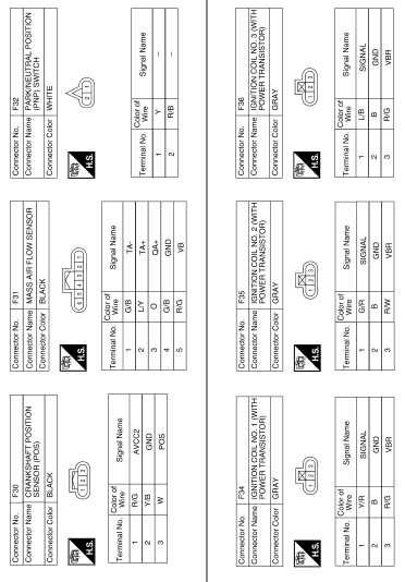
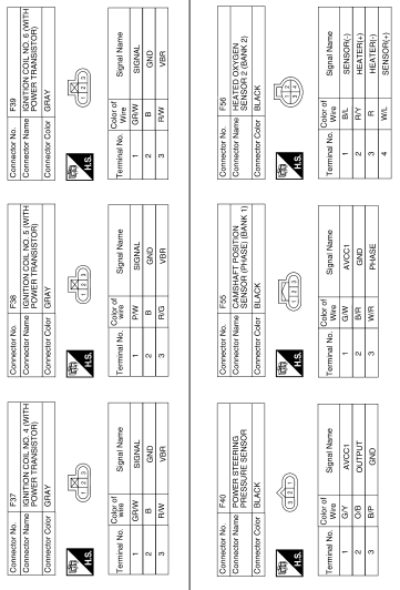
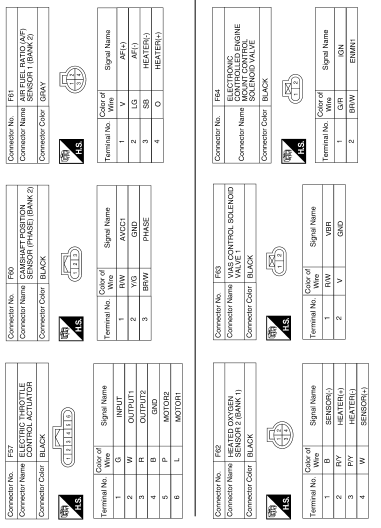
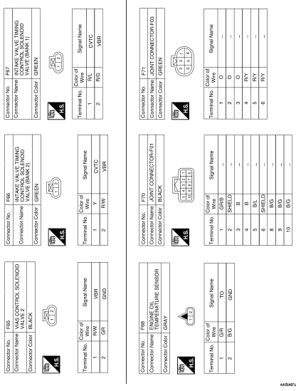
TERMINAL LAYOUT
PHYSICAL VALUES
NOTE: • ECM is located in the engine room left side near battery.
• Specification data are reference values.
• Pulse signal is measured by CONSULT-III.
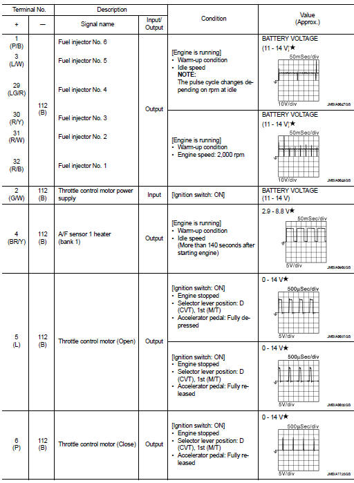
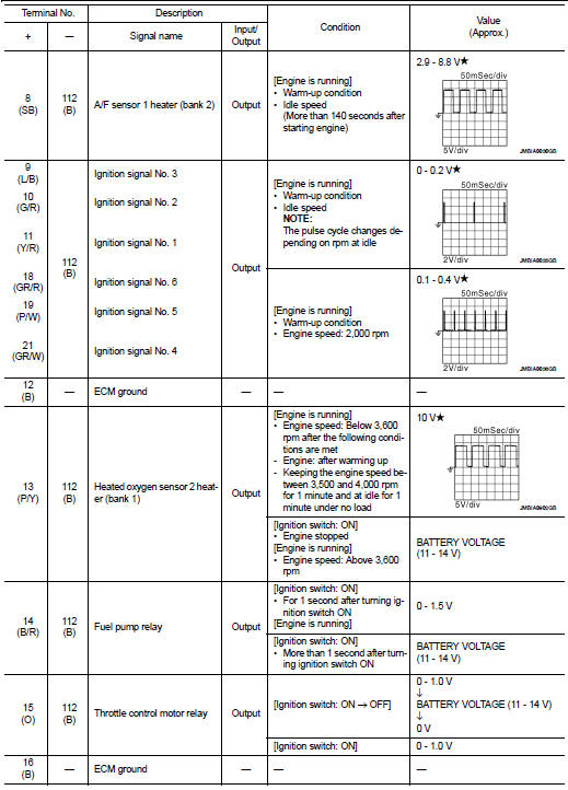
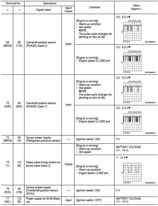
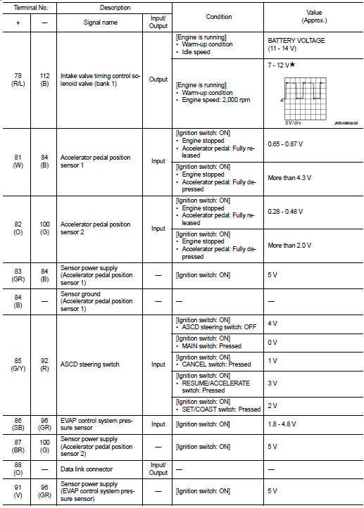
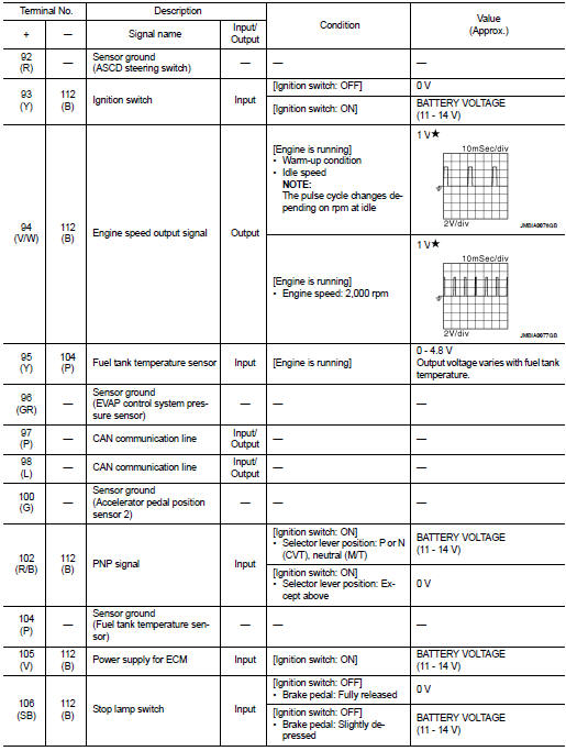
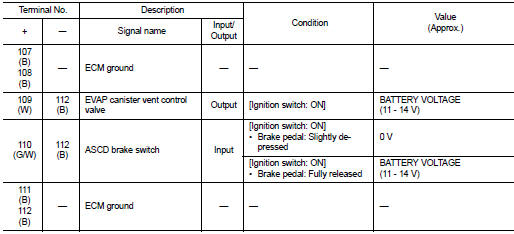
 : Average voltage for pulse
signal (Actual pulse signal can be confirmed by oscilloscope.)
*1: This may vary depending on internal resistance of the tester.
: Average voltage for pulse
signal (Actual pulse signal can be confirmed by oscilloscope.)
*1: This may vary depending on internal resistance of the tester.
*2: Before measuring the terminal voltage, confirm that the battery is fully charged. Refer to PG-3, "How to Handle Battery".
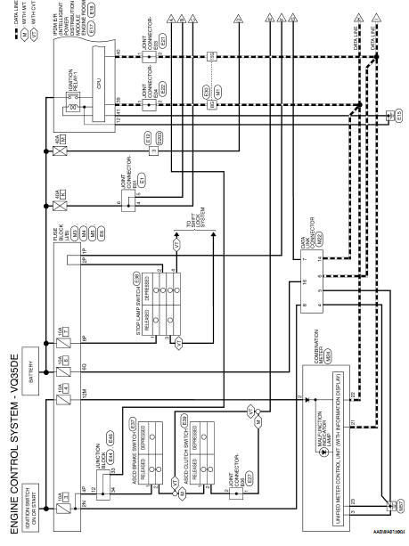
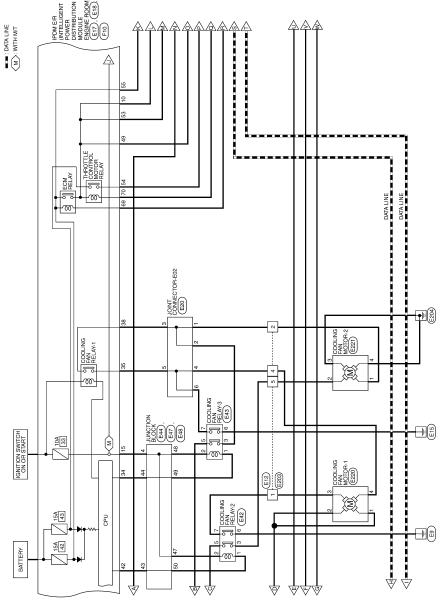
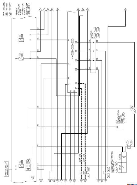
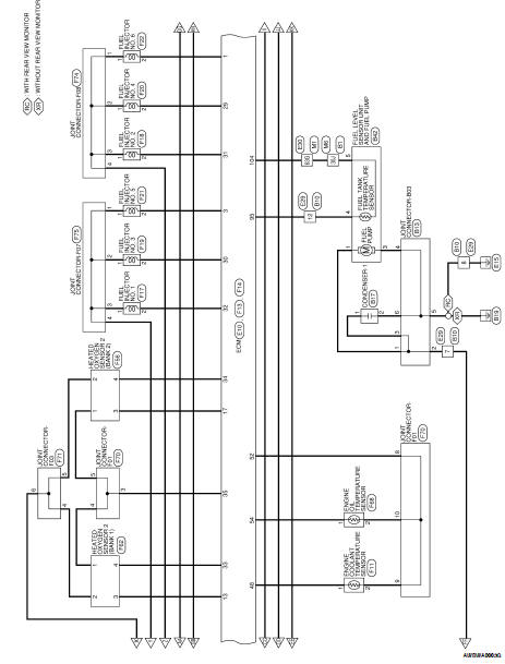
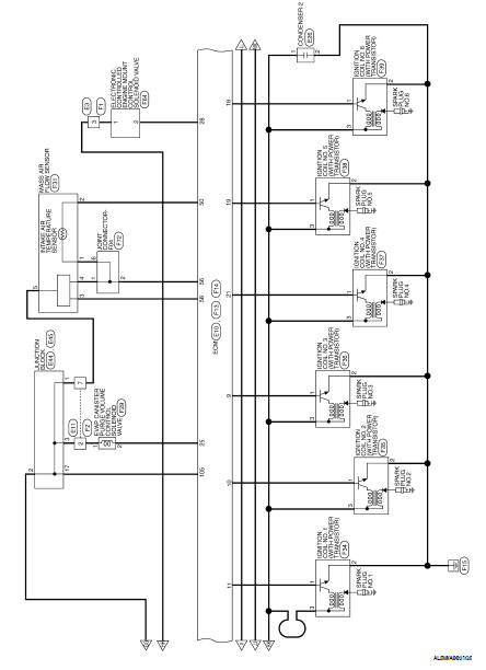
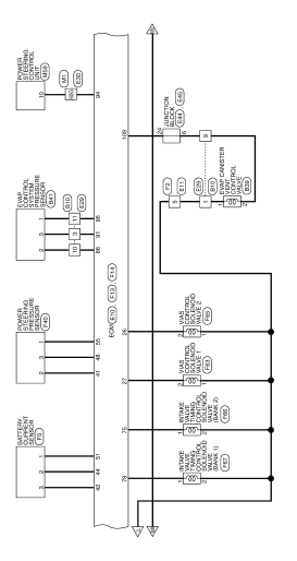
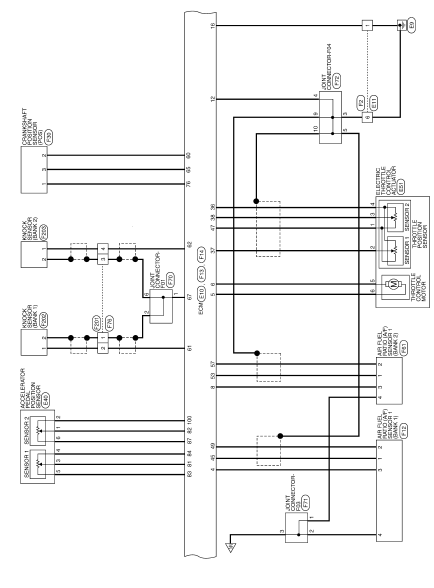
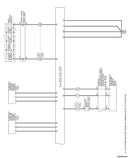
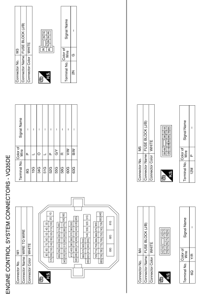
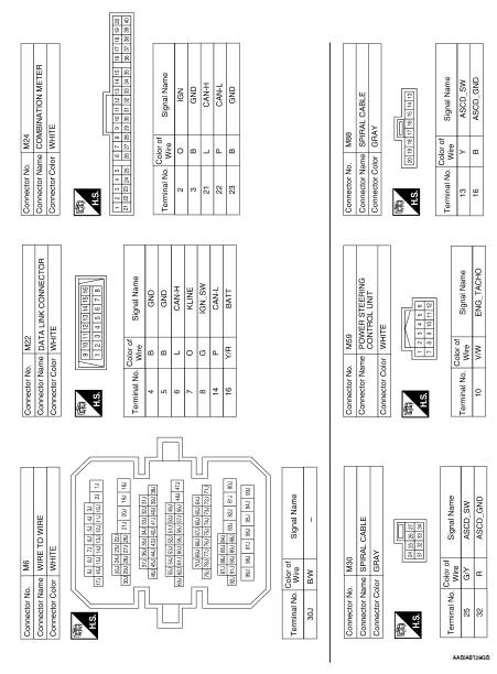
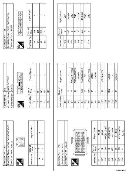
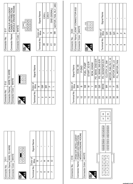
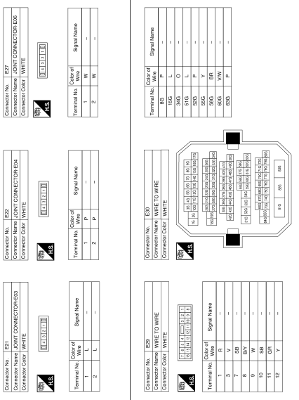
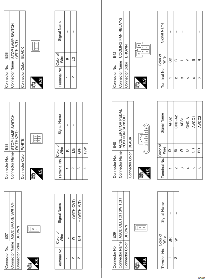
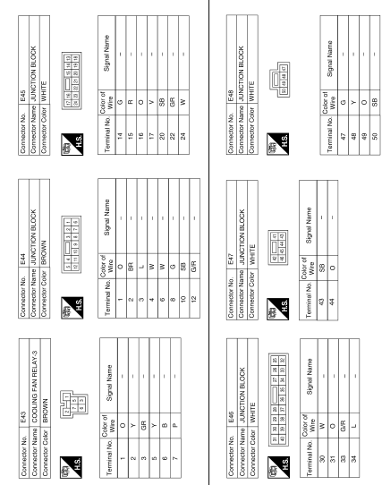
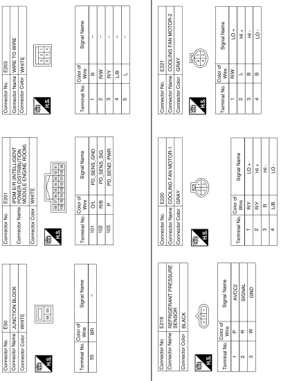
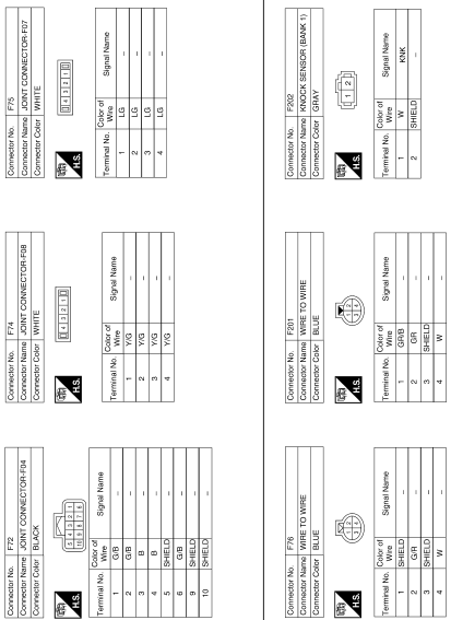
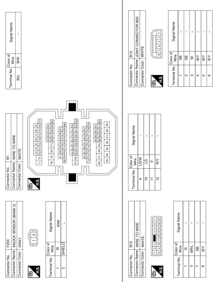
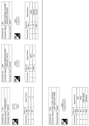
Wiring Diagram
Wiring Diagram—ENGINE CONTROL SYSTEM—
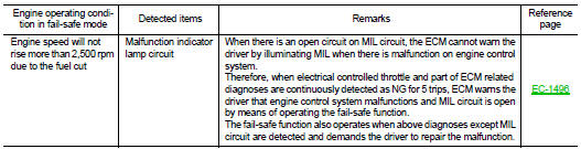
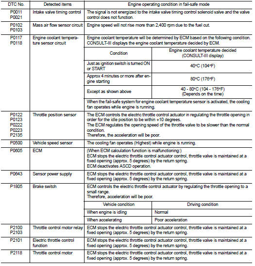
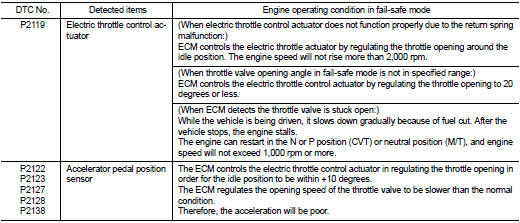
Fail-safe
NON DTC RELATED ITEM
DTC RELATED ITEM
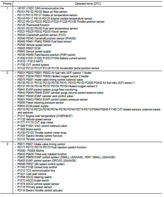
DTC Inspection Priority Chart
If some DTCs are displayed at the same time, perform inspections one by one based on the following priority chart.
DTC Index
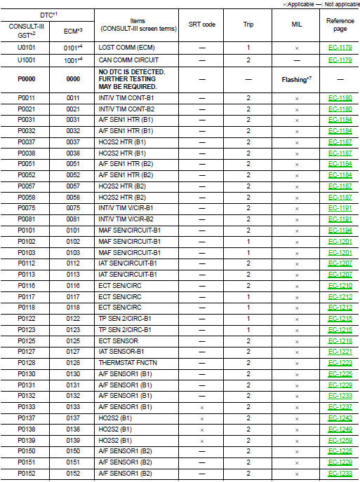
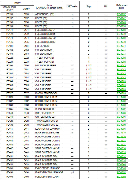
*1: 1st trip DTC No. is the same as DTC No.
*2: This number is prescribed by SAE J2012.
*3: In Diagnostic Test Mode II (Self-diagnostic results), this number is controlled by NISSAN.
*4: The troubleshooting for this DTC needs CONSULT-III.
*5: When the fail-safe operations for both self-diagnoses occur, the MIL illuminates.
*6: SRT code will not be set if the self-diagnostic result is NG.
*7: When the ECM is in the mode that displays SRT status, MIL may flash. For the details, refer to “How to Display SRT Status”.
How to Set SRT Code
To set all SRT codes, self-diagnoses for the items indicated above must be performed one or more times.
Each diagnosis may require a long period of actual driving under various conditions.

Perform corresponding DTC Confirmation Procedure one by one based on Performance Priority in the table on “SRT Item”.

The most efficient driving pattern in which SRT codes can be properly set is explained below. The driving pattern should be performed one or more times to set all SRT codes.
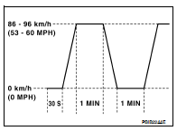
DRIVING PATTERN
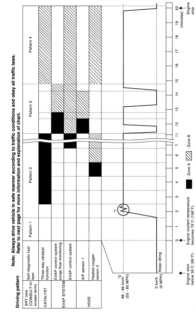
• The time required for each diagnosis varies with road surface conditions, weather, altitude, individual driving habits, etc.
Zone A refers to the range where the time, required for the diagnosis under normal conditions*, is the shortest.
Zone B refers to the range where the diagnosis can still be performed if the diagnosis is not completed within zone A.
*: Normal conditions refer to the following:
• Sea level
• Flat road
Ambient air temperature: 20 - 30°C (68 - 86°F) • Diagnosis is performed as quickly as possible under normal conditions.
Under different conditions [For example: ambient air temperature other than 20 - 30°C (68 - 86°F)], diagnosis may also be performed.
Pattern 1: • The engine is started at the engine coolant temperature of −10 to 35°C (14 to 95°F) (where the voltage between the ECM terminal 46 and ground is 3.0 - 4.3 V).
• The engine must be operated at idle speed until the engine coolant temperature is greater than 70°C (158°F) (where the voltage between the ECM terminal 46 and ground is lower than 1.4 V).
• The engine is started at the fuel tank temperature of warmer than 0°C (32°F) (where the voltage between the ECM terminal 95 and ground is less than 4.1 V).
Pattern 2: • When steady-state driving is performed again even after it is interrupted, each diagnosis can be conducted.
In this case, the time required for diagnosis may be extended.
Pattern 3: • Operate vehicle following the driving pattern shown in the figure.
• Release the accelerator pedal during deceleration of vehicle speed from 90 km/h (56 MPH) to 0 km/h (0 MPH).
Pattern 4: • The accelerator pedal must be held very steady during steadystate driving.
• If the accelerator pedal is moved, the test must be conducted again.
*1: Depress the accelerator pedal until vehicle speed is 90 km/h (56 MPH), then release the accelerator pedal and keep it released for more than 10 seconds. Depress the accelerator pedal until vehicle speed is 90 km/h (56 MPH) again.
*2: Checking the vehicle speed with GST is advised.
Suggested Transmission Gear Position for CVT Models
Set the selector lever in the D position.
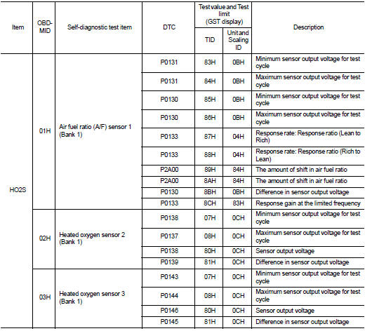
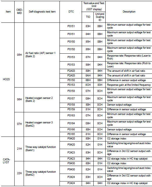
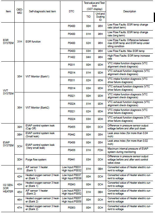
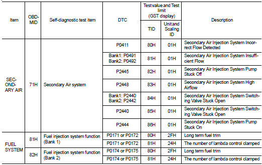
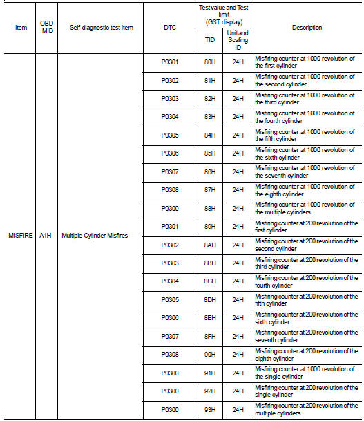
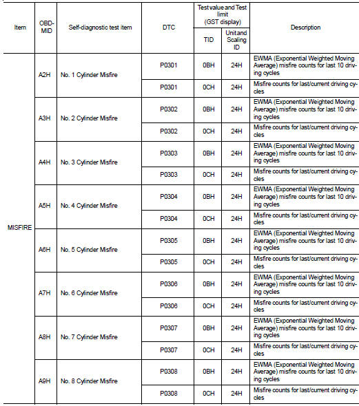
Test Value and Test Limit
The following is the information specified in Service $06 of SAE J1979.
The test value is a parameter used to determine whether a system/circuit diagnostic test is OK or NG while being monitored by the ECM during self-diagnosis. The test limit is a reference value which is specified as the maximum or minimum value and is compared with the test value being monitored.
These data (test value and test limit) are specified by On Board Monitor ID(OBDMID), Test ID (TID), Unit and Scaling ID and can be displayed on the GST screen.
The items of the test value and test limit will be displayed with GST screen which items are provided by the ECM. (eg., if bank 2 is not applied on this vehicle, only the items of bank 1 are displayed)
 Variable induction air system
 Symptom diagnosis