Nissan Altima (L32) 2007-2012 Service Manual: Electrical load signal
Description
The electrical load signal (Headlamp switch signal, rear window defogger switch signal, etc.) is transferred via the CAN communication.
Component Function Check
1.CHECK REAR WINDOW DEFOGGER SWITCH FUNCTION
1. Turn ignition switch ON.
2. Connect CONSULT-III and select “DATA MONITOR” mode.
3. Select “LOAD SIGNAL” and check indication under the following conditions.
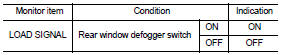
Is the inspection result normal? YES >> GO TO 2.
NO >> Go to EC-1478, "Diagnosis Procedure".
2.CHECK LIGHTING SWITCH FUNCTION
Check “LOAD SIGNAL” indication under the following conditions.
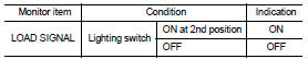
Is the inspection result normal? YES >> GO TO 3.
NO >> Go to EC-1478, "Diagnosis Procedure".
3.CHECK HEATER FAN CONTROL SWITCH FUNCTION
Select “HEATER FAN SW” and check indication under the following conditions.
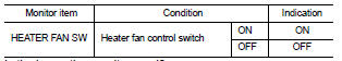
Is the inspection result normal? YES >> INSPECTION END
NO >> Go to EC-1478, "Diagnosis Procedure".
Diagnosis Procedure
1.INSPECTION START
Confirm the malfunctioning circuit (rear window defogger, headlamp or heater fan). Refer to EC-1478, "Component Function Check".
Which circuit is related to the incident? Rear window defogger>>GO TO 2.
Headlamp>>GO TO 3.
Heater fan>>GO TO 4.
2.CHECK REAR WINDOW DEFOGGER SYSTEM
Refer to DEF-3, "Work Flow".
>> INSPECTION END
3.CHECK HEADLAMP SYSTEM
Refer to EXL-4, "Work Flow".
>> INSPECTION END
4.CHECK HEATER FAN CONTROL SYSTEM
Refer to HAC-4, "Work Flow" (automatic air conditioner) or HAC-101, "Work Flow" (manual air conditioner).
>> INSPECTION END
 Cooling fan
 Electronic controlled engine mount