Nissan Altima (L32) 2007-2012 Service Manual: Engine control system
System Diagram
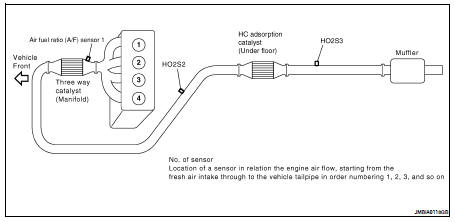
System Description
ECM performs various controls such as fuel injection control and ignition timing control.
Component Parts Location
1. Intake valve timing control solenoid valve
2. Ignition coil (with power transistor) and spark plug
3. Knock sensor, Crankshaft position sensor (POS)
4. Air fuel ratio (A/F) sensor 1
5. Camshaft position sensor (PHASE)
6. Engine coolant temperature sensor
7. Park/neutral position (PNP) switch
8. ECM
9. Refrigerant pressure sensor
10. Battery current sensor
11. IPDM E/R
12. Mass air flow sensor (with intake temperature sensor)
13. Tumble control valve actuator
14. EVAP service port
15. Electric throttle control actuator (with built in throttle position sensor and throttle control motor)
16. EVAP canister purge volume control solenoid valve
17. Fuel injector
18. Power steering pressure sensor
1. Battery
2. Fuel pump fuse (15A)
3. IPDM E/R
4. Brake master cylinder
5. Engine ground
6. Air cleaner assembly
7. Mass air flow sensor (with intake air temperature sensor)
8. Radiator hose (upper)
9. Engine coolant temperature sensor
10. Intake air duct
11. Camshaft position sensor (PHASE)
12. Tie rod (RH)
16. Crankshaft position sensor (POS)
17. Drive shaft (RH)

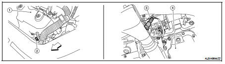
1. Exhaust manifold cover
2. Air fuel ratio (A/F) sensor 1
3. Heated oxygen sensor 2 (This illustration is a view from under vehicle.)
4. Engine oil pan

1. EVAP service port
2. Intake air duct
3. EVAP canister purge volume control solenoid valve
4. Intake manifold collector
5. Park/neutral position (PNP) switch (CVT) (This illustration is view with air cleaner assembly removed.)
6. Park/neutral position (PNP) switch (M/T) (This illustration is view with air cleaner assembly removed.)
7. Intake valve timing control solenoid valve (This illustration is view with engine removed.)
8. Exhaust manifold cover
9. Air fuel ratio (A/F) sensor 1
10. Air fuel ratio (A/F) sensor 1 harness connector
11. Heated oxygen sensor 2 (This illustration is view from under vehicle.)
12. Heated oxygen sensor 2 harness connector (This illustration is view from under vehicle.)
13. Engine oil pan
14. Heated oxygen sensor 3 (This illustration is view form under vehicle.)
15. Heated oxygen sensor 3 harness connector (This illustration is view from under vehicle.)
1. Thermostat housing
2. Tumble control valve actuator
3. Throttle valve (This illustration is view with intake air duct removed.)
4. Electric throttle control actuator
5. Fuel injector harness connector
6. Condenser-2
7. Radiator hose (upper)
8. Battery
9. ECM
10. Fuel level sensor unit and fuel pump harness connector (This illustration is view with rear seat cushion and inspection hole cover removed.)
11. Fuel level sensor unit and fuel pump assembly
12. Fuel pressure regulator
13. Fuel tank temperature sensor
14. EVAP control system pressure sensor (This illustration is view with rear suspension member removed.)
15. EVAP canister vent control valve (This illustration is view with rear suspension member removed.)
16. EVAP canister (This illustration is view with rear suspension member removed.)
1. No.1 ignition coil
2. Cooling fan motor-1 harness connector
3. Cooling fan motor-2 harness connector
4. Refrigerant pressure sensor
5. Accelerator pedal position sensor
6. ASCD brake switch
7. Stop lamp switch
8. Brake pedal
9. ASCD clutch switch
10. Clutch pedal
11. ASCD steering switch
12. CANSEC switch
13. RESUME/ACCELERATE switch
14. SET/COAST switch
15. MAIN switch
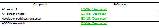
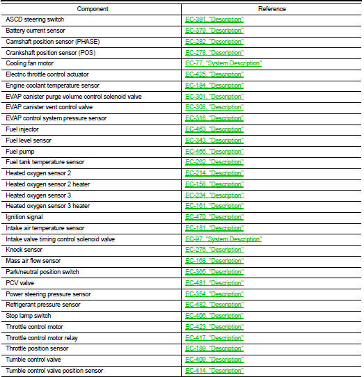
Component Description
 Function diagnosis
 Multiport fuel injection system