Nissan Altima (L32) 2007-2012 Service Manual: Function diagnosis
EPS SYSTEM
System Diagram
CONTROL DIAGRAM
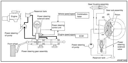
System Description
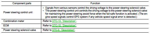
• The EPS system controls the power steering solenoid valve through the power steering control unit.
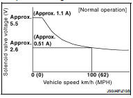
• The valve driving voltage to control the power steering solenoid valve varies according to the vehicle speed.
OPERATION PRINCIPLE
During Parking (When Turning The Steering Wheel To The Right)
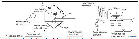
1. Power steering solenoid valve is closed while a vehicle is stopped.
2. Pinion "1R", "2R" and "3R" are closed depending on steering torque of steering wheel.
3. Oil pressure "P" in the gear housing assembly is the sum of oil pressures occurred in "2R" and "3R". This results in a light steering force because of high pressure.
During High-speed Operation
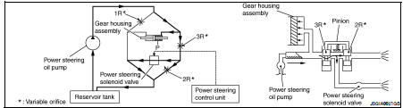
1. Power steering solenoid valve is opened during high-speed operation.
2. Pinion "1R", "2R" and "3R" are closed depending on steering torque of steering wheel.
3. Oil pressure "2R" does not occur because the power steering solenoid valve is on full throttle.
4. Oil pressure "P" in the gear housing assembly includes only oil pressure occurred in "3R" and results in a heavy steering force.
Component Parts Location
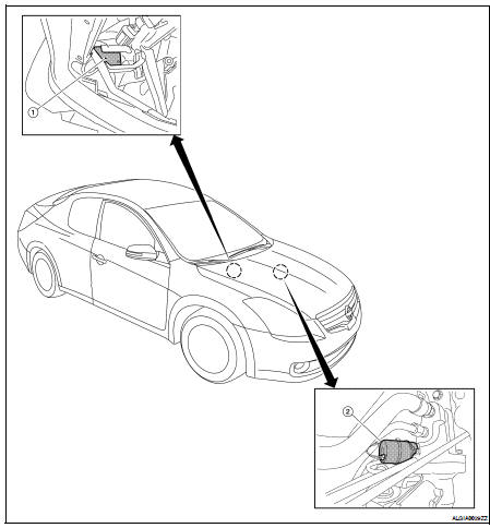
1. Power steering control unit M59 (view with glove box removed)
2. Power steering solenoid valve E14
Component Description
 Basic inspection
 Component diagnosis